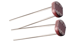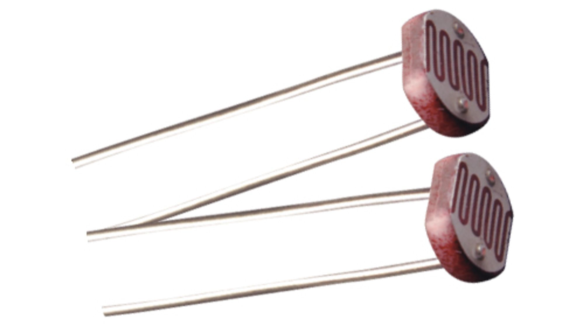
Photoresistors (Light Dependent Resistors – LDRs)
Photoresistors, commonly known as Light Dependent Resistors (LDRs), are electronic components that change their resistance in response to the intensity of light. This article explores their operation, applications, advantages, and disadvantages, offering a comprehensive understanding for electronics enthusiasts and professionals.
Basic Principle
Photoresistors are semiconductor devices whose electrical resistance decreases as the intensity of incident light increases. This behavior results from the generation of charge carriers (electrons and holes) when light strikes the semiconductor material of the photoresistor.
Material and Structure
- Semiconductor Materials: Most photoresistors are made of cadmium sulfide (CdS) or cadmium selenide (CdSe), which have specific energy band gaps. These gaps determine the energy required to move electrons from the valence band to the conduction band, allowing electrical conduction.
- Sensitivity to Wavelengths: Photoresistors are most sensitive to wavelengths around 550 nm, corresponding to green light, making them ideal for detecting visible light.
Key Applications
- Protection Circuits
Used in protection systems to detect light variations, triggering safety mechanisms during abrupt changes in lighting. - Alarm Systems
Often employed in alarm systems that activate when light is interrupted or suddenly increased, signaling the presence of an intruder. - Light Meters
Instruments like photometers and environmental light meters utilize photoresistors for accurate readings of ambient light intensity, critical in photography and horticulture. - Presence Detection
Integrated into timer-based circuits, photoresistors detect light presence to activate devices such as lamps for predetermined durations.
Advantages of Photoresistors
- Simplicity: Easy to use and integrate into circuits.
- Cost-Effective: Affordable and widely available.
- Robustness: Operate reliably across a broad range of environmental conditions.
- High Light Sensitivity: Particularly responsive to visible light, essential for precise intensity detection.
Disadvantages of Photoresistors
- Slow Response Time: Changes in resistance lag behind variations in light intensity, limiting use in fast-switching applications.
- Temperature Sensitivity: Resistance can fluctuate with temperature changes, affecting measurement accuracy in variable environments.
- Limited Precision: Less accurate compared to alternatives like photodiodes and phototransistors.
Final Considerations
Photoresistors are essential in many light-dependent systems due to their simplicity, affordability, and robustness. However, their limitations, such as slow response time and temperature sensitivity, should be considered when designing circuits. For high-precision applications, alternative light sensors may be more suitable.
FAQ
- What is a photoresistor?
A photoresistor, or LDR, is a component that changes its resistance based on the intensity of incident light. - How does a photoresistor work?
It uses semiconductor materials to generate charge carriers when exposed to light, reducing resistance as light intensity increases. - What materials are used in photoresistors?
Common materials include cadmium sulfide (CdS) and cadmium selenide (CdSe). - What are common applications for photoresistors?
They are used in alarm systems, light meters, presence detectors, and protection circuits. - What are the advantages of photoresistors?
Simplicity, low cost, robustness, and high sensitivity to visible light. - What are the drawbacks of photoresistors?
Slow response time, sensitivity to temperature, and limited precision compared to photodiodes and phototransistors. - Can photoresistors be used in temperature-variable environments?
While robust, their resistance may fluctuate with temperature changes, introducing measurement errors. - How are photoresistors integrated into circuits?
Typically paired with bias resistors and other components to create light-sensitive devices or systems. - What is the wavelength sensitivity of photoresistors?
They are most sensitive to wavelengths near 550 nm (green light). - What distinguishes photoresistors from photodiodes and phototransistors?
Photoresistors change resistance with light, photodiodes generate current, and phototransistors amplify light-generated current.
Photoresistors (Light Dependent Resistors – LDRs) Read More »