Circuit Analysis
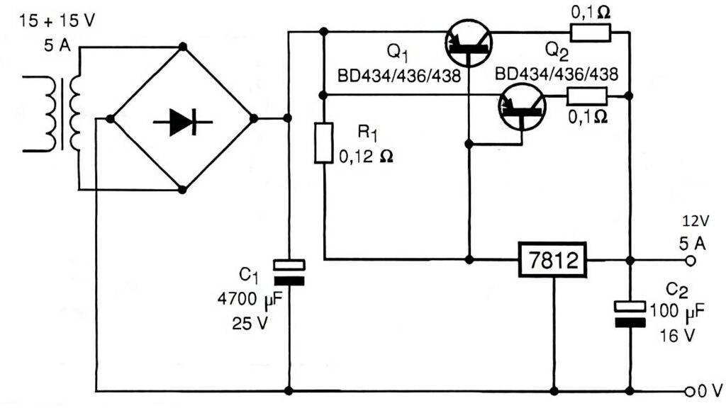
This circuit is a 12V, 5A regulated power supply, based on the 7812 voltage regulator and BD434/436/438 transistors to increase the available output current. Let’s analyze how it works:
Rectification and Filtering The transformer provides a 15V-0-15V AC voltage with a current capacity of up to 5A.
The bridge rectifier converts the alternating current (AC) into direct current (DC).
Capacitor C1 (4700 µF, 25V) acts as a filter, smoothing out the rectified voltage and reducing ripple.
Voltage Regulation (7812) The 7812 voltage regulator is an integrated circuit (IC) that maintains a constant 12V output, but it has a current limit, typically around 1 to 1.5A.
To support 5A output, the circuit uses power transistors in a Darlington configuration.
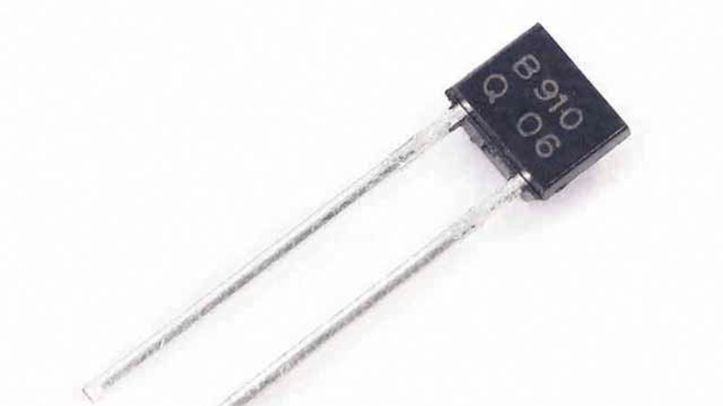
Current Boost with BD434/436/438 Transistors Transistors Q1 and Q2 (BD434/436/438) function as current amplifiers.
The output current from the 7812 triggers the base of Q1, which in turn triggers Q2.
The 0.1Ω emitter resistors help balance the current between the transistors.
Output Capacitor (C2 – 100µF, 16V) This capacitor filters the output voltage, improving stability and reducing noise.
Component List
Reference | Component | Specification |
|---|---|---|
Transformer | 15V-0-15V | 5A |
Bridge Rectifier | Diodes | 5A rating |
C1 | Electrolytic Capacitor | 4700µF / 25V |
7812 | Voltage Regulator | 12V / 1A |
Q1, Q2 | PNP Transistor | BD434 / BD436 / BD438 |
R1 | Resistor | 0.12Ω |
Emitter Resistors | Resistors | 0.1Ω / 5W |
C2 | Electrolytic Capacitor | 100µF / 16V |
Summary
This circuit converts 15V AC into regulated 12V DC, supporting currents up to 5A. The 7812 ensures voltage regulation, while the transistors boost the current capacity. The capacitors assist in filtering, providing a more stable output.