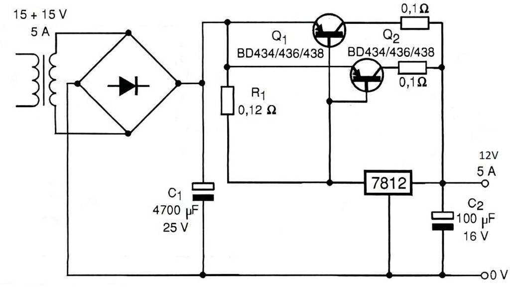
This circuit is a 12V, 5A regulated power supply, based on the 7812 voltage regulator and BD434/436/438 transistors to increase the available output current. Let’s analyze how it works:
Rectification and Filtering The transformer provides a 15V-0-15V AC voltage with a current capacity of up to 5A.
The bridge rectifier converts the alternating current (AC) into direct current (DC).
Capacitor C1 (4700 µF, 25V) acts as a filter, smoothing out the rectified voltage and reducing ripple.
Voltage Regulation (7812) The 7812 voltage regulator is an integrated circuit (IC) that maintains a constant 12V output, but it has a current limit, typically around 1 to 1.5A.
To support 5A output, the circuit uses power transistors in a Darlington configuration.
Current Boost with BD434/436/438 Transistors Transistors Q1 and Q2 (BD434/436/438) function as current amplifiers.
The output current from the 7812 triggers the base of Q1, which in turn triggers Q2.
The 0.1Ω emitter resistors help balance the current between the transistors.
Output Capacitor (C2 – 100µF, 16V) This capacitor filters the output voltage, improving stability and reducing noise.
Component List
Reference
Component
Specification
Transformer
15V-0-15V
5A
Bridge Rectifier
Diodes
5A rating
C1
Electrolytic Capacitor
4700µF / 25V
7812
Voltage Regulator
12V / 1A
Q1, Q2
PNP Transistor
BD434 / BD436 / BD438
R1
Resistor
0.12Ω
Emitter Resistors
Resistors
0.1Ω / 5W
C2
Electrolytic Capacitor
100µF / 16V
Summary
This circuit converts 15V AC into regulated 12V DC, supporting currents up to 5A. The 7812 ensures voltage regulation, while the transistors boost the current capacity. The capacitors assist in filtering, providing a more stable output.
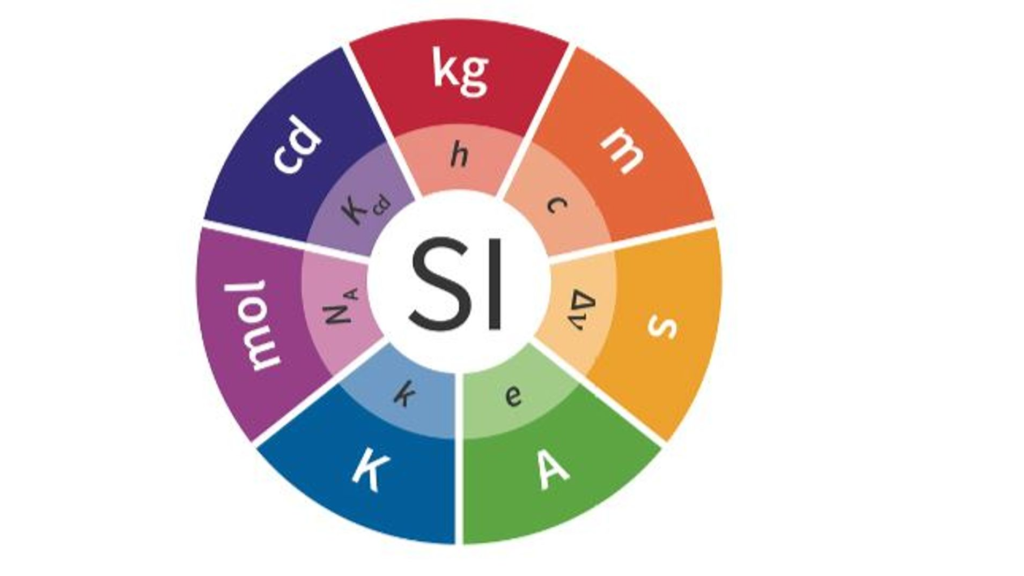
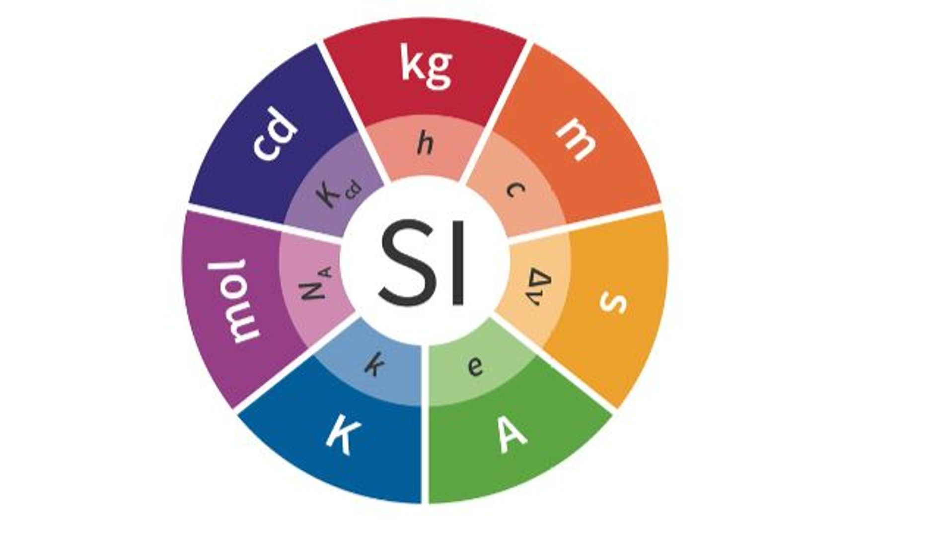
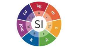
In the field of engineering, it is essential that theoretical results be compared with experimental ones and that different designs be evaluated quantitatively. This is only possible in an effective manner when there is a standardization of the measurement units used. The International System of Units (SI) plays a central role in this process, being widely adopted by engineers and engineering societies worldwide. This uniformity in measurements facilitates communication among multidisciplinary teams and ensures that everyone is “speaking the same language” in terms of measurement units.
The SI system consists of seven fundamental quantities, each with its corresponding basic unit and symbol, as illustrated in Table 1.1:
Table 1.1 – Fundamental Quantities of the International System of Units (SI)
Quantity
Basic Unit
Symbol
Length
meter
m
Mass
kilogram
kg
Time
second
s
Electric current
ampere
A
Thermodynamic temperature
kelvin
K
Amount of substance
mole
mol
Luminous intensity
candela
cd
These basic units serve as the foundation for other units, known as derived units, which are combinations of the fundamental ones. Some of these derived units, such as force (newton), energy (joule), and power (watt), are frequently used in engineering calculations and analyses. Below, Table 1.2 presents some of the main derived units in SI:
Table 1.2 – Derived Units in the International System of Units (SI)
Quantity
Unit Name
Symbol
Formula
Frequency
hertz
Hz
s⁻¹
Force
newton
N
kg × m/s²
Energy or Work
joule
J
N × m
Power
watt
W
J/s
Electric charge
coulomb
C
A × s
Electric potential
volt
V
J/C
Electrical resistance
ohm
Ω
V/A
Electrical conductance
siemens
S
A/V
Electrical capacitance
farad
F
C/V
Magnetic flux
weber
Wb
V × s
Inductance
henry
H
Wb/A
To make the units more practical for everyday calculations, especially when dealing with very small or large quantities, SI allows the use of prefixes that represent powers of 10. These prefixes, which facilitate the adaptation of basic units, are shown in Table 1.3:
Table 1.3 – Standardized SI Prefixes Representing Powers of 10
Prefix
Symbol
Power of 10
atto
a
10⁻¹⁸
femto
f
10⁻¹⁵
pico
p
10⁻¹²
nano
n
10⁻⁹
micro
μ
10⁻⁶
milli
m
10⁻³
centi
c
10⁻²
deci
d
10⁻¹
deca
da
10¹
hecto
h
10²
kilo
k
10³
mega
M
10⁶
giga
G
10⁹
tera
T
10¹²
In practice, engineers generally prefer the prefixes representing powers of 10 that are divisible by 3, such as milli (10⁻³), kilo (10³), and mega (10⁶). This is because these prefixes allow for adjusting measurements into a more convenient range, typically between 1 and 1,000. For example, instead of expressing a time as 0.00001 seconds, it is more common to use 10 microseconds (10 μs).
The Role of Circuit Analysis in Engineering
Circuit analysis is a central element in the development of electrical engineering designs. The design process begins with identifying a need, which leads to the formulation of clear specifications. From these specifications, the design concept is developed and translated into a mathematical model, which in electrical engineering usually takes the form of a circuit.
The circuit model is composed of ideal components, which are mathematical representations of real electrical components, such as batteries or resistors. Analyzing this circuit allows for predicting the system’s behavior and comparing the results with the design specifications. When theoretical and experimental results are in agreement, the next step is to build a physical prototype, which will undergo rigorous testing to validate its performance.
Consistent use of SI units throughout the design process ensures accuracy in measurements and facilitates communication between teams, making the development process more efficient and reliable.
FAQ:
What is the International System of Units (SI)?
The SI is a standardized system of measurement units widely adopted globally, essential for standardizing measurements in engineering and other sciences.
What are the basic units of the SI?
The basic units of the SI include meter (m) for length, kilogram (kg) for mass, second (s) for time, ampere (A) for electric current, kelvin (K) for temperature, mole for amount of substance, and candela (cd) for luminous intensity.
What are derived units in SI?
Derived units are combinations of the SI’s fundamental units, such as newton (N) for force, joule (J) for energy, and watt (W) for power.
Why is the use of prefixes in SI important?
SI prefixes, like milli (10⁻³) and kilo (10³), make it easier to adapt units to a practical range in calculations, especially when dealing with very small or very large quantities.
What is the role of circuit analysis in electrical engineering?
Circuit analysis is crucial for predicting the behavior of electrical systems, ensuring the design meets specifications through mathematical models based on ideal components.
How does SI facilitate communication among engineers?
Consistent use of SI ensures that all engineering teams use the same unit language, which is crucial for accuracy and efficiency in projects.
If you liked this article, consider sharing it on social media, this will help to spread knowledge, leave your comment below so we can know your opinion.
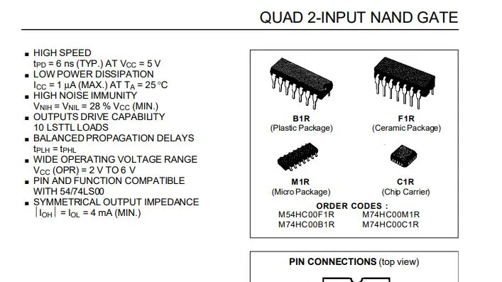
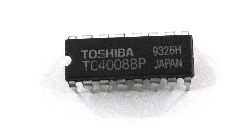
CMOS (Complementary Metal-Oxide-Semiconductor) integrated circuits are foundational in modern electronics due to their energy efficiency, low power dissipation, and high integration density. These circuits are widely used in a vast array of applications, from mobile devices to industrial equipment. Below are some key characteristics and applications:
Structure and Operation
Fabrication Technology: Based on complementary metal-oxide-semiconductor technology, using complementary pairs of MOSFET transistors (N-MOS and P-MOS).
Form Factor: Available in various packages, including DIP (Dual In-line Package), SOIC (Small Outline Integrated Circuit), and QFP (Quad Flat Package), enabling easy integration into different types of PCBs (Printed Circuit Boards).
Key Characteristics
Power Consumption: Known for their low power consumption, especially in static states, making them ideal for battery-powered devices.
Operating Speed: Capable of operating at high frequencies, making them suitable for high-speed applications.
Operating Voltage: Typically operate within voltages between 1.8V and 5V, with some variants supporting lower or higher voltages.
Integration Density: Allow the integration of a large number of transistors on a single chip, facilitating the creation of complex circuits.
Noise Resistance: Highly immune to noise and interference, improving the reliability of circuits.
Typical Applications
Processors and Microcontrollers: Used in central processing units (CPUs) and microcontrollers due to their energy efficiency and high integration capability.
Memory Devices: Found in memory chips, including RAM and ROM, thanks to their high integration density and low energy consumption.
Mobile Devices: Essential in smartphones, tablets, and wearables, where energy efficiency is crucial.
Industrial Equipment: Employed in various industrial systems, including process control and automation, due to their robustness and reliability.
Consumer Electronics: Widely used in a variety of consumer electronic products, such as televisions, digital cameras, and audio systems.
Advantages
Energy Efficiency: They offer low power consumption, particularly in low-activity states.
High Integration: Enable the creation of highly complex circuits on a single chip.
Low Cost: Benefit from highly mature manufacturing processes, resulting in low production costs.
High Reliability: Resistant to noise with a low failure rate, making them highly reliable for various applications.
Disadvantages
Sensitivity to ESD: They can be sensitive to electrostatic discharge (ESD), requiring careful handling during manufacturing and assembly.
Performance at High Temperatures: Performance may be affected at very high temperatures, requiring proper thermal management.
FAQ:
What are CMOS integrated circuits, and why are they important? CMOS integrated circuits are key to modern electronics due to their low power consumption, high density, and ability to integrate complex circuits on a single chip. They’re used in a wide range of applications, from mobile devices to industrial systems.
What are the typical applications of CMOS circuits? CMOS circuits are used in processors, memory devices, mobile devices, industrial equipment, and consumer electronics due to their efficiency, small size, and high reliability.
What are the key advantages of CMOS technology? CMOS technology offers energy efficiency, high integration density, low cost, and high reliability, making it ideal for a broad range of electronic applications.
What are the disadvantages of CMOS circuits? CMOS circuits are sensitive to electrostatic discharge (ESD) and may have reduced performance in high-temperature environments, requiring appropriate handling and thermal management.
How are CMOS integrated circuits used in processors and memory? CMOS circuits are extensively used in processors and microcontrollers because they allow for the integration of complex functionality while consuming minimal power, making them ideal for these high-performance applications.
CI
Description
Pins
4000
2 three-input NOR gates + 1 inverter
14
4001
4 two-input NOR gates
14
4002
2 four-input NOR gates
14
4009
6 inverting buffers
16
4010
6 non-inverting buffers
16
4011
4 two-input NAND gates
14
4013
2 D-type flip-flops
14
4019
4 selectable AND/OR gates
16
4020
14-stage binary counter/divider
16
4026
Decade counter with 7-segment decoder
16
4030
4 two-input XOR gates
14
4034
3-stage 8-bit bidirectional shift register
24
4035
4-bit parallel shift register
16
4040
12-stage binary counter with carry
16
4041
4 buffers with original and complementary output
14
4042
4 clocked D-type latches
16
4043
4 three-stage latches
16
4046
PLL (Phase-Locked Loop)
16
4047
Low-power astable/monostable multivibrator
14
4048
8 programmable/expandable 3-state gates
16
4049
6 inverting buffers
16
4050
6 non-inverting buffers
16
4051
8-channel analog multiplexer/demultiplexer
16
4052
4-channel dual analog multiplexer/demultiplexer
16
4060
14-stage binary counter with ripple, carry, and oscillator
16
4066
4 bilateral switches
14
4069
6 inverters
14
4070
4 XOR gates
14
4072
2 four-input OR gates
14
4073
3 three-input AND gates
14
4076
4 three-stage register outputs
16
4077
4 XNOR gates
14
4081
4 two-input AND gates
14
4089
4-bit binary multiplier
14
4093
4 two-input NAND gates Schmitt Trigger
16
4094
8-stage shift register and memory
16
4099
8-bit addressable latch
16
40106
6 Schmitt Trigger inverters
14
40160
4-bit synchronous decade counter with asynchronous reset
16
40161
4-bit synchronous binary counter with asynchronous reset
16
40162
4-bit synchronous decade counter with synchronous reset
16
40163
4-bit synchronous binary counter with synchronous reset
16
40193
4-bit Up/Down binary counter
16
4503
6 three-state buffers
16
4510
BCD Up/Down counter
16
4511
BCD to 7-segment decoder
16
4512
8-input multiplexer with 3-stage output
16
4514
16-to-1 decoder/demultiplexer with latch inputs
24
4516
Up/Down binary counter
16
4519
4 two-input multiplexers
16
4520
2 binary counters
16
4528
2 monostable multivibrators
16
4529
Analog data selector 2 of 4 channels or 1 of 8 channels
Ceramic capacitors are widely used passive electronic components that store and release electrical energy. Known for their excellent electrical characteristics, compact size, and high performance in various applications, these capacitors are an essential part of modern electronic devices. Below are the main features and applications of ceramic capacitors, adapted to the standards and terminology relevant to the United States and the United Kingdom.
Structure and Operation
Dielectric Material: Ceramic capacitors use ceramic as the dielectric material, providing a high dielectric constant, which contributes to their compact size and effectiveness.
Shape: Available in various shapes, including SMD (Surface-Mount Device) and radial, which allows for easy integration onto printed circuit boards (PCBs).
Key Characteristics
Capacitance: Ceramic capacitors are available in a wide range of capacitances, from a few picofarads (pF) up to hundreds of microfarads (µF).
Tolerance: The tolerance generally ranges from ±1% to ±10%, providing high precision for many applications.
Rated Voltage: These capacitors can operate at different voltages, typically from 10V to 500V, with options available for even higher voltages.
Operating Temperature: The operational temperature range is typically from -55°C to +125°C, with some variants capable of withstanding even more extreme temperatures.
Stability: Ceramic capacitors exhibit excellent thermal stability and resistance to humidity variations, maintaining their electrical properties over time.
Typical Applications
Decoupling: Used for decoupling circuits, helping to stabilize voltage and reduce unwanted noise.
Signal Filtering: Employed in high-frequency filters due to their low Equivalent Series Resistance (ESR) and low dielectric losses.
Oscillators: Utilized in oscillator circuits because of their ability to maintain a stable capacitance value.
High-Frequency Circuits: Ideal for high-frequency applications where low ESR and excellent high-frequency performance are crucial.
Advantages
High Capacitance in Small Volume: These capacitors offer high capacitance in a compact size, making them ideal for modern, space-constrained devices.
Low Inductance: Especially useful in high-frequency applications due to their low inductance, ensuring better performance.
Cost: Ceramic capacitors are typically economical and widely available, making them a popular choice for various applications.
Disadvantages
Capacitance Variation with Temperature: Some classes of ceramic capacitors, especially Class II and III, may experience significant capacitance variation with temperature changes.
Microphonics: In certain applications, ceramic capacitors may exhibit microphonics, where mechanical vibrations translate into electrical variations, leading to potential performance issues.
Frequently Asked Questions (FAQ)
1. What is the difference between Class I, II, and III ceramic capacitors?
Class I capacitors have the most stable temperature and voltage characteristics but lower capacitance. They are ideal for precision applications.
Class II and III capacitors provide higher capacitance but exhibit more significant capacitance variation with temperature. They are often used where cost and size are more important than precision.
2. Can ceramic capacitors be used in high-frequency circuits?
Yes, ceramic capacitors are ideal for high-frequency applications due to their low ESR and inductance, which make them effective at filtering high-frequency signals.
3. Why do ceramic capacitors sometimes experience microphonics?
Microphonics can occur in ceramic capacitors because mechanical vibrations can induce electrical noise. This can be an issue in sensitive audio or high-precision circuits.
4. What is the typical lifespan of a ceramic capacitor?
Ceramic capacitors typically have a long lifespan when used within their specified voltage and temperature ranges. However, their performance may degrade if exposed to extreme conditions for prolonged periods.
If you liked this article, consider sharing it on social media, this will help to spread knowledge, leave your comment below so we can know your opinion.
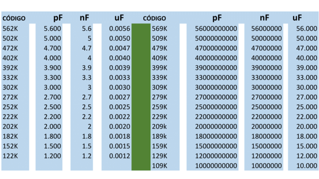
Description of Values in Picofarads (pF) / Nanofarads (nF)
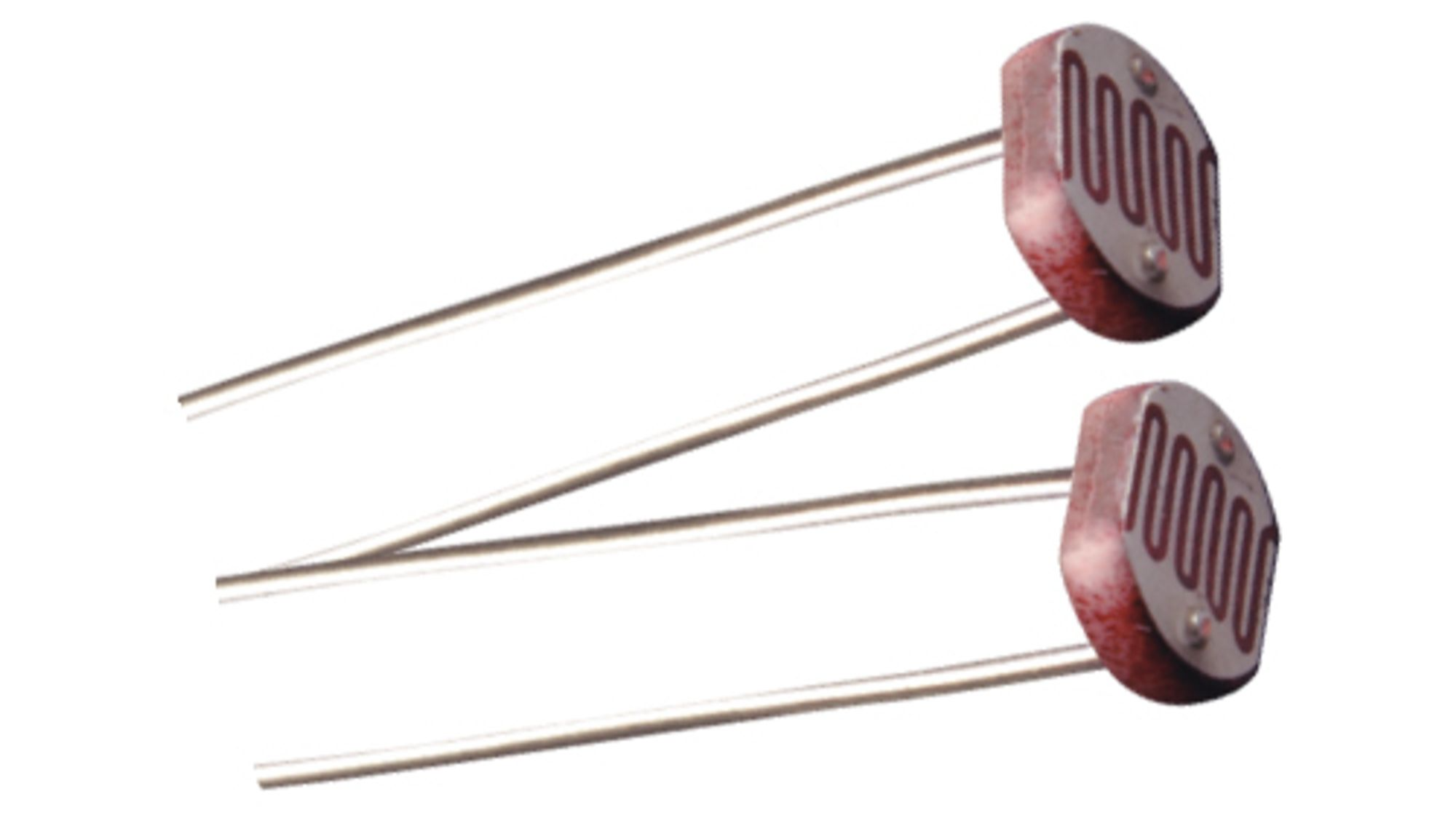
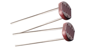
Photoresistors, commonly known as Light Dependent Resistors (LDRs), are electronic components that change their resistance in response to the intensity of light. This article explores their operation, applications, advantages, and disadvantages, offering a comprehensive understanding for electronics enthusiasts and professionals.
Basic Principle
Photoresistors are semiconductor devices whose electrical resistance decreases as the intensity of incident light increases. This behavior results from the generation of charge carriers (electrons and holes) when light strikes the semiconductor material of the photoresistor.
Material and Structure
Semiconductor Materials: Most photoresistors are made of cadmium sulfide (CdS) or cadmium selenide (CdSe), which have specific energy band gaps. These gaps determine the energy required to move electrons from the valence band to the conduction band, allowing electrical conduction.
Sensitivity to Wavelengths: Photoresistors are most sensitive to wavelengths around 550 nm, corresponding to green light, making them ideal for detecting visible light.
Key Applications
Protection Circuits Used in protection systems to detect light variations, triggering safety mechanisms during abrupt changes in lighting.
Alarm Systems Often employed in alarm systems that activate when light is interrupted or suddenly increased, signaling the presence of an intruder.
Light Meters Instruments like photometers and environmental light meters utilize photoresistors for accurate readings of ambient light intensity, critical in photography and horticulture.
Presence Detection Integrated into timer-based circuits, photoresistors detect light presence to activate devices such as lamps for predetermined durations.
Advantages of Photoresistors
Simplicity: Easy to use and integrate into circuits.
Cost-Effective: Affordable and widely available.
Robustness: Operate reliably across a broad range of environmental conditions.
High Light Sensitivity: Particularly responsive to visible light, essential for precise intensity detection.
Disadvantages of Photoresistors
Slow Response Time: Changes in resistance lag behind variations in light intensity, limiting use in fast-switching applications.
Temperature Sensitivity: Resistance can fluctuate with temperature changes, affecting measurement accuracy in variable environments.
Limited Precision: Less accurate compared to alternatives like photodiodes and phototransistors.
Final Considerations
Photoresistors are essential in many light-dependent systems due to their simplicity, affordability, and robustness. However, their limitations, such as slow response time and temperature sensitivity, should be considered when designing circuits. For high-precision applications, alternative light sensors may be more suitable.
FAQ
What is a photoresistor? A photoresistor, or LDR, is a component that changes its resistance based on the intensity of incident light.
How does a photoresistor work? It uses semiconductor materials to generate charge carriers when exposed to light, reducing resistance as light intensity increases.
What materials are used in photoresistors? Common materials include cadmium sulfide (CdS) and cadmium selenide (CdSe).
What are common applications for photoresistors? They are used in alarm systems, light meters, presence detectors, and protection circuits.
What are the advantages of photoresistors? Simplicity, low cost, robustness, and high sensitivity to visible light.
What are the drawbacks of photoresistors? Slow response time, sensitivity to temperature, and limited precision compared to photodiodes and phototransistors.
Can photoresistors be used in temperature-variable environments? While robust, their resistance may fluctuate with temperature changes, introducing measurement errors.
How are photoresistors integrated into circuits? Typically paired with bias resistors and other components to create light-sensitive devices or systems.
What is the wavelength sensitivity of photoresistors? They are most sensitive to wavelengths near 550 nm (green light).
What distinguishes photoresistors from photodiodes and phototransistors? Photoresistors change resistance with light, photodiodes generate current, and phototransistors amplify light-generated current.
BD series transistors are renowned for their ability to handle medium to high power, making them a staple in applications requiring robust current and voltage control. This article delves into the BDxxx transistor series, highlighting their characteristics, typical applications, and providing a detailed specification table.
Introduction to BD Series Transistors
BD series transistors are designed to handle higher currents and voltages compared to other series like BC. They find use in various applications, such as power amplifiers, voltage regulators, and switching circuits. Their robustness and reliability make them a popular choice in projects requiring consistent performance under demanding conditions.
BD Series Transistor Specifications
Below is a table summarizing the main BD series transistor codes, along with their specifications and typical applications:
Code
Type
Vceo (V)
Ic (A)
Ptot (W)
hFE
Typical Applications
BD135
NPN
45
1.5
12.5
40-250
Power Amplifiers, Drivers
BD136
PNP
45
1.5
12.5
40-250
Power Amplifiers, Drivers
BD137
NPN
60
1.5
12.5
40-250
Power Amplifiers, Drivers
BD138
PNP
60
1.5
12.5
40-250
Power Amplifiers, Drivers
BD139
NPN
80
1.5
12.5
40-250
Audio Amplifiers, Regulators
BD140
PNP
80
1.5
12.5
40-250
Audio Amplifiers, Regulators
BD175
NPN
60
4
40
15-75
Voltage Regulators, Amplifiers
BD176
PNP
60
4
40
15-75
Voltage Regulators, Amplifiers
BD243
NPN
100
6
65
20-100
High-Power Audio Amplifiers
BD244
PNP
100
6
65
20-100
High-Power Audio Amplifiers
Column Explanation
Code: The transistor identification within the BD series.
Type: Indicates whether the transistor is NPN or PNP.
Vceo (V): Maximum voltage between collector and emitter.
Ic (A): Maximum collector current.
Ptot (W): Maximum power dissipation.
hFE: Current gain (beta factor).
Typical Applications: Common use cases for the transistor.
Detailed Overview of Key BD Series Transistors
BD135, BD136, BD137, BD138
Type: NPN (BD135, BD137) and PNP (BD136, BD138).
Applications: Ideal for power amplifiers and drivers.
Characteristics:
BD135/BD136: Operates up to 45V; suitable for circuits with moderate voltage requirements.
BD137/BD138: Operates up to 60V; used in higher voltage applications, such as motor drivers.
BD139, BD140
Type: NPN (BD139) and PNP (BD140).
Applications: Frequently used in audio amplifiers and voltage regulators.
Characteristics:
BD139: Handles up to 80V; common in medium-power audio amplification.
BD140: Complementary to BD139, ideal for complementary pair configurations.
BD175, BD176
Type: NPN (BD175) and PNP (BD176).
Applications: Preferred in voltage regulators and high-current amplifiers.
Characteristics: Can handle up to 4A of current and dissipate 40W of power.
BD243, BD244
Type: NPN (BD243) and PNP (BD244).
Applications: High-power audio amplifiers requiring up to 6A and 100V.
Characteristics: Frequently used in high-performance audio systems.
Common Applications of BD Series Transistors
1. Power Amplifiers
BD135, BD136, BD137, and BD138 are widely used in power amplifiers due to their ability to manage higher currents and voltages, making them ideal for amplifier output stages.
2. Voltage Regulators
BD139, BD140, BD175, and BD176 are preferred in voltage regulation circuits, ensuring stable voltage output for precision applications.
3. High-Current Drivers
Transistors like BD243 and BD244 excel in driving high-current devices such as motors and large loads without performance degradation.
4. Audio Amplification
BD139, BD140, BD243, and BD244 are staples in high-power audio amplification, ensuring excellent sound quality and output power.
5. Prototyping and Educational Projects
The robustness and accessibility of BD transistors make them ideal for learning and experimentation in medium- to high-power circuit designs.
Conclusion
BDxxx transistors are versatile and reliable components, well-suited for a variety of electronic applications. Whether in power amplifiers, voltage regulators, high-current drivers, or audio systems, these transistors deliver consistent performance. Their role in electronic design remains pivotal, especially in medium to high-power scenarios.
FAQ
What are BD series transistors typically used for?
They are used in applications like power amplifiers, voltage regulators, audio systems, and high-current drivers.
What is the difference between BD139 and BD140?
BD139 is an NPN transistor, while BD140 is its PNP complement, often used together in complementary configurations.
Can BD series transistors handle high currents?
Yes, certain models like BD243 and BD244 can handle currents up to 6A.
Are BD series transistors suitable for audio applications?
Absolutely, BD139, BD140, BD243, and BD244 are frequently used in high-power audio amplification.