In the realm of electronics, the conversion of alternating current (AC) to direct current (DC) is essential for powering a wide variety of electronic circuits. This process is carried out by rectifiers, devices that use diodes to transform the sinusoidal voltage into a pulsating form, which is subsequently filtered to produce a steady DC voltage. In this article, we will delve into the half-wave rectifier, one of the simplest and most fundamental types of rectifiers.

What is a Half-Wave Rectifier?
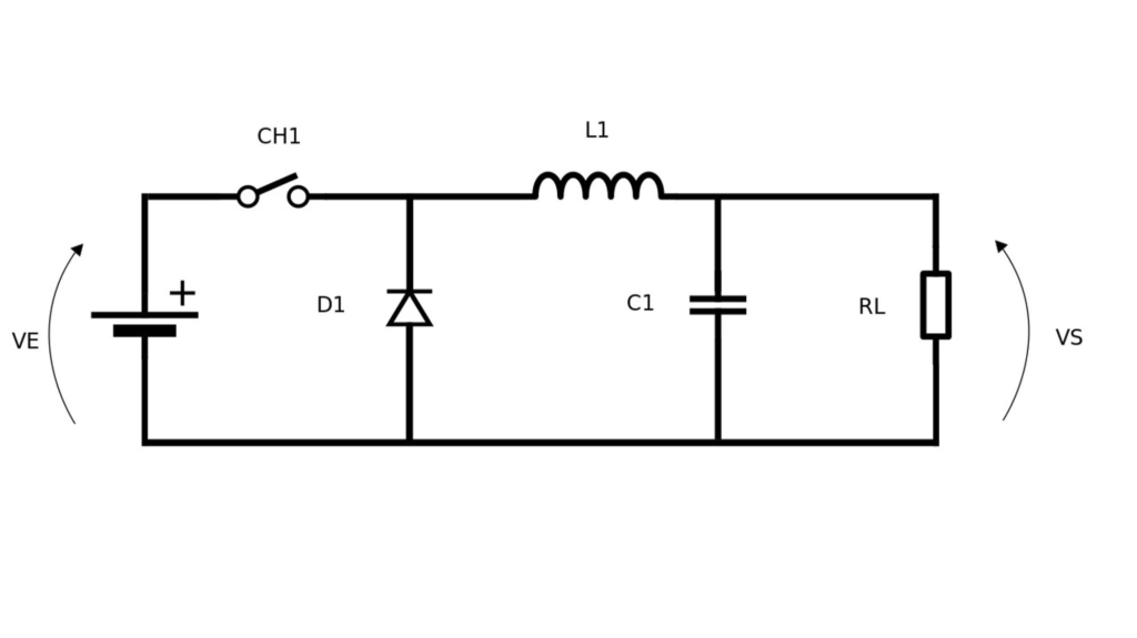
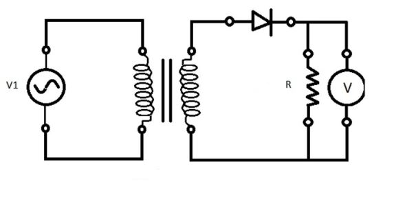
A half-wave rectifier is a circuit that employs a single diode to convert only one half-cycle of the AC input voltage into DC voltage. This type of rectifier consists of a diode connected at the output of a transformer. During operation, it allows only the positive half-cycles of the input voltage to pass while blocking the negative half-cycles.
Components and Operation
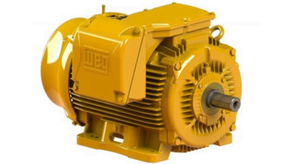
- Transformer: Adjusts the AC source voltage to the desired level.
- Diode: Conducts current during positive half-cycles and blocks it during negative half-cycles.
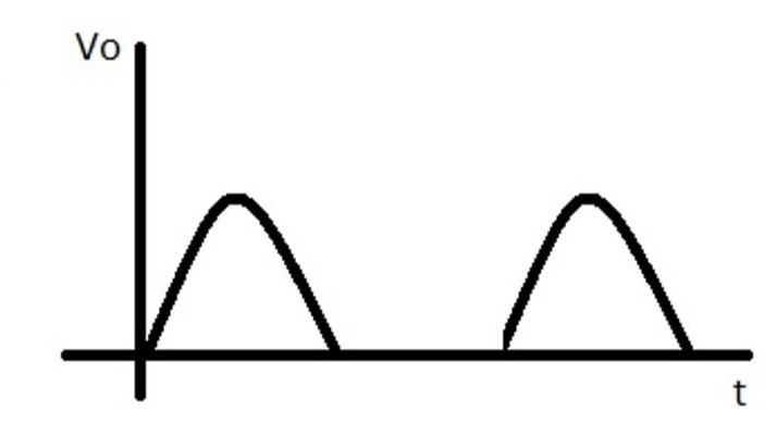
When the input voltage (V_in) is positive, the diode conducts, and the load voltage (V_L) is nearly equal to the input voltage, minus a small voltage drop across the diode (approximately 0.7V for silicon diodes). During negative half-cycles, the diode does not conduct, resulting in zero voltage across the load.
Output Waveform – Half-Wave Rectifier
Key Formulas
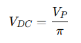
- Average Voltage (V_DC): The average DC output voltage can be calculated as:

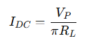
where VPV_PVP is the peak input voltage. - Average Current (I_DC): The average current through the load is:

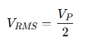
where RLR_LRL is the load resistance. - RMS Voltage (V_RMS): For a peak value significantly greater than 0.7V, the RMS voltage is approximately:

Practical Example
Consider a circuit with the following parameters:
- Peak input voltage (VP): 17V
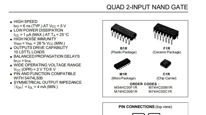
- Diode: 1N4001
- Load resistance (RL): 100Ω
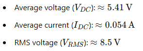
Resulting values:
Sizing the Diode
To ensure safe operation, select the diode based on these electrical limits:
- Peak Reverse Voltage (PIV): Must exceed VP.
- Average Forward Current (I_AV): Must exceed IDC.
- RMS Voltage (V_RMS): Must exceed the input RMS voltage.
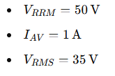
For example, the 1N4001 diode has the following limits:
Conclusion
The half-wave rectifier is a simple and effective introduction to the rectification process. While it is not as efficient as other topologies, such as full-wave rectifiers, it serves as an excellent starting point for understanding the fundamentals of AC-to-DC conversion. This knowledge is crucial for designing and maintaining a wide array of electronic circuits.

FAQ
What is a half-wave rectifier?
A half-wave rectifier is an electronic circuit that converts alternating current (AC) into direct current (DC) using a single diode, passing only the positive half-cycles of the input voltage and blocking the negative ones.
How does a half-wave rectifier work?
It uses a diode to conduct electric current during the positive half-cycles of the input voltage and blocks current during the negative half-cycles, resulting in a pulsating DC output.
What are the main components of a half-wave rectifier?
- Transformer: Adjusts the input AC voltage.
- Diode: Allows conduction during positive half-cycles.
- Load Resistance (R_L): Receives the rectified voltage.
What are the advantages of a half-wave rectifier?
- Simple design.
- Low cost due to the use of a single diode.
- Good for educational and experimental purposes.
What are the disadvantages of a half-wave rectifier?
- Low efficiency since only half of the input cycle is utilized.
- High output ripple requiring additional filtering.
- Pulsating current can generate more heat in the load.
How do I choose the right diode for a half-wave rectifier?
Consider these parameters:
- Peak Reverse Voltage (PIV): Higher than the input voltage peak.
- Forward Current (I_AV): Exceeding the average load current.
- Power Dissipation: Should align with the circuit’s power needs.
What are typical applications of a half-wave rectifier?
- Low-power power supplies.
- Signal rectification in radios and communication equipment.
- Educational circuit demonstrations.
How can I improve the efficiency of a half-wave rectifier?
- Use a full-wave rectifier or a bridge rectifier.
- Add capacitors to filter the ripple.
- Employ inductors to further smooth the output current.