Generic selectors
Exact matches only
Search in title
Search in content
Post Type Selectors

Eletrônica Analógica

Sistema Internacional de Unidades

In the field of engineering, it is essential that theoretical results be compared with experimental ones and that different designs be evaluated quantitatively. This is only possible in an effective manner when there is a standardization of the measurement units used. The International System of Units (SI) plays a central role in this process, being widely adopted by engineers and engineering societies worldwide. This uniformity in measurements facilitates communication among multidisciplinary teams and ensures that everyone is “speaking the same language” in terms of measurement units.

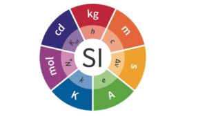
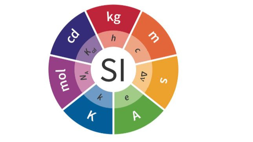
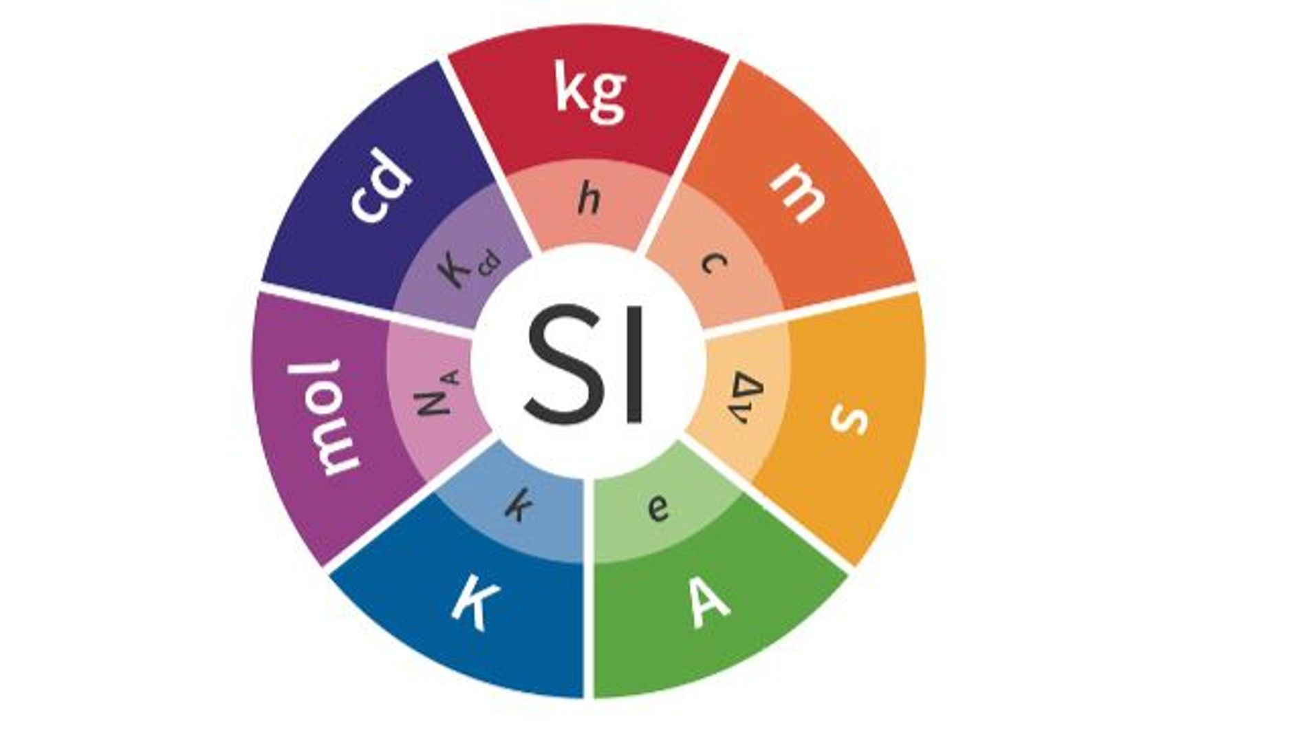
The SI system consists of seven fundamental quantities, each with its corresponding basic unit and symbol, as illustrated in Table 1.1:

Table 1.1 – Fundamental Quantities of the International System of Units (SI)

Quantity

Basic Unit

Symbol

Length

meter

m

Mass

kilogram

kg

Time

second

s

Electric current

ampere

A

Thermodynamic temperature

kelvin

K

Amount of substance

mole

mol

Luminous intensity

candela

cd

These basic units serve as the foundation for other units, known as derived units, which are combinations of the fundamental ones. Some of these derived units, such as force (newton), energy (joule), and power (watt), are frequently used in engineering calculations and analyses. Below, Table 1.2 presents some of the main derived units in SI:

Table 1.2 – Derived Units in the International System of Units (SI)

Quantity

Unit Name

Symbol

Formula

Frequency

hertz

Hz

s⁻¹

Force

newton

N

kg × m/s²

Energy or Work

joule

J

N × m

Power

watt

W

J/s

Electric charge

coulomb

C

A × s

Electric potential

volt

V

J/C

Electrical resistance

ohm

Ω

V/A

Electrical conductance

siemens

S

A/V

Electrical capacitance

farad

F

C/V

Magnetic flux

weber

Wb

V × s

Inductance

henry

H

Wb/A

To make the units more practical for everyday calculations, especially when dealing with very small or large quantities, SI allows the use of prefixes that represent powers of 10. These prefixes, which facilitate the adaptation of basic units, are shown in Table 1.3:

Table 1.3 – Standardized SI Prefixes Representing Powers of 10

Prefix

Symbol

Power of 10

atto

a

10⁻¹⁸

femto

f

10⁻¹⁵

pico

p

10⁻¹²

nano

n

10⁻⁹

micro

μ

10⁻⁶

milli

m

10⁻³

centi

c

10⁻²

deci

d

10⁻¹

deca

da

10¹

hecto

h

10²

kilo

k

10³

mega

M

10⁶

giga

G

10⁹

tera

T

10¹²

In practice, engineers generally prefer the prefixes representing powers of 10 that are divisible by 3, such as milli (10⁻³), kilo (10³), and mega (10⁶). This is because these prefixes allow for adjusting measurements into a more convenient range, typically between 1 and 1,000. For example, instead of expressing a time as 0.00001 seconds, it is more common to use 10 microseconds (10 μs).

The Role of Circuit Analysis in Engineering

Circuit analysis is a central element in the development of electrical engineering designs. The design process begins with identifying a need, which leads to the formulation of clear specifications. From these specifications, the design concept is developed and translated into a mathematical model, which in electrical engineering usually takes the form of a circuit.

The circuit model is composed of ideal components, which are mathematical representations of real electrical components, such as batteries or resistors. Analyzing this circuit allows for predicting the system’s behavior and comparing the results with the design specifications. When theoretical and experimental results are in agreement, the next step is to build a physical prototype, which will undergo rigorous testing to validate its performance.

Consistent use of SI units throughout the design process ensures accuracy in measurements and facilitates communication between teams, making the development process more efficient and reliable.

FAQ:

What is the International System of Units (SI)?
The SI is a standardized system of measurement units widely adopted globally, essential for standardizing measurements in engineering and other sciences.

What are the basic units of the SI?
The basic units of the SI include meter (m) for length, kilogram (kg) for mass, second (s) for time, ampere (A) for electric current, kelvin (K) for temperature, mole for amount of substance, and candela (cd) for luminous intensity.

What are derived units in SI?
Derived units are combinations of the SI’s fundamental units, such as newton (N) for force, joule (J) for energy, and watt (W) for power.

Why is the use of prefixes in SI important?
SI prefixes, like milli (10⁻³) and kilo (10³), make it easier to adapt units to a practical range in calculations, especially when dealing with very small or very large quantities.

What is the role of circuit analysis in electrical engineering?
Circuit analysis is crucial for predicting the behavior of electrical systems, ensuring the design meets specifications through mathematical models based on ideal components.

How does SI facilitate communication among engineers?
Consistent use of SI ensures that all engineering teams use the same unit language, which is crucial for accuracy and efficiency in projects.

If you liked this article, consider sharing it on social media, this will help to spread knowledge, leave your comment below so we can know your opinion.

International System of Units (SI) Read More »

Fotorresistor

Photoresistors (Light Dependent Resistors – LDRs)

Photoresistors, commonly known as Light Dependent Resistors (LDRs), are electronic components that change their resistance in response to the intensity of light. This article explores their operation, applications, advantages, and disadvantages, offering a comprehensive understanding for electronics enthusiasts and professionals.

Basic Principle

Photoresistors are semiconductor devices whose electrical resistance decreases as the intensity of incident light increases. This behavior results from the generation of charge carriers (electrons and holes) when light strikes the semiconductor material of the photoresistor.

Material and Structure

  • Semiconductor Materials: Most photoresistors are made of cadmium sulfide (CdS) or cadmium selenide (CdSe), which have specific energy band gaps. These gaps determine the energy required to move electrons from the valence band to the conduction band, allowing electrical conduction.
  • Sensitivity to Wavelengths: Photoresistors are most sensitive to wavelengths around 550 nm, corresponding to green light, making them ideal for detecting visible light.

Key Applications

  1. Protection Circuits
    Used in protection systems to detect light variations, triggering safety mechanisms during abrupt changes in lighting.
  2. Alarm Systems
    Often employed in alarm systems that activate when light is interrupted or suddenly increased, signaling the presence of an intruder.
  3. Light Meters
    Instruments like photometers and environmental light meters utilize photoresistors for accurate readings of ambient light intensity, critical in photography and horticulture.
  4. Presence Detection
    Integrated into timer-based circuits, photoresistors detect light presence to activate devices such as lamps for predetermined durations.

Advantages of Photoresistors

  • Simplicity: Easy to use and integrate into circuits.
  • Cost-Effective: Affordable and widely available.
  • Robustness: Operate reliably across a broad range of environmental conditions.
  • High Light Sensitivity: Particularly responsive to visible light, essential for precise intensity detection.

Disadvantages of Photoresistors

  • Slow Response Time: Changes in resistance lag behind variations in light intensity, limiting use in fast-switching applications.
  • Temperature Sensitivity: Resistance can fluctuate with temperature changes, affecting measurement accuracy in variable environments.
  • Limited Precision: Less accurate compared to alternatives like photodiodes and phototransistors.

Final Considerations

Photoresistors are essential in many light-dependent systems due to their simplicity, affordability, and robustness. However, their limitations, such as slow response time and temperature sensitivity, should be considered when designing circuits. For high-precision applications, alternative light sensors may be more suitable.

FAQ

  1. What is a photoresistor?
    A photoresistor, or LDR, is a component that changes its resistance based on the intensity of incident light.
  2. How does a photoresistor work?
    It uses semiconductor materials to generate charge carriers when exposed to light, reducing resistance as light intensity increases.
  3. What materials are used in photoresistors?
    Common materials include cadmium sulfide (CdS) and cadmium selenide (CdSe).
  4. What are common applications for photoresistors?
    They are used in alarm systems, light meters, presence detectors, and protection circuits.
  5. What are the advantages of photoresistors?
    Simplicity, low cost, robustness, and high sensitivity to visible light.
  6. What are the drawbacks of photoresistors?
    Slow response time, sensitivity to temperature, and limited precision compared to photodiodes and phototransistors.
  7. Can photoresistors be used in temperature-variable environments?
    While robust, their resistance may fluctuate with temperature changes, introducing measurement errors.
  8. How are photoresistors integrated into circuits?
    Typically paired with bias resistors and other components to create light-sensitive devices or systems.
  9. What is the wavelength sensitivity of photoresistors?
    They are most sensitive to wavelengths near 550 nm (green light).
  10. What distinguishes photoresistors from photodiodes and phototransistors?
    Photoresistors change resistance with light, photodiodes generate current, and phototransistors amplify light-generated current.

Photoresistors (Light Dependent Resistors – LDRs) Read More »

Resistor

A resistor is a passive electronic component used to limit the flow of electric current in a circuit. Its electrical resistance is measured in ohms (Ω). By offering resistance to the flow of electrons, resistors help regulate electric current and protect other sensitive components from damage caused by excess current.

Characteristics and Properties of Resistors

Resistors have several characteristics and properties that are essential for their use in electronic circuits. Some of the key aspects to consider are:

  • Nominal Resistance: This is the resistor’s declared value, expressed in ohms. It determines the amount of opposition to the flow of electric current that the resistor provides.
  • Tolerance: Tolerance is a specification that indicates the allowed variation from the nominal resistance value. It is expressed as a percentage and defines the precision of the resistor.
  • Nominal Power: The nominal power rating determines the maximum amount of energy the resistor can safely dissipate. Selecting a resistor with an appropriate power rating is crucial to avoid overheating.
  • Temperature Rating: The temperature rating specifies the range of temperatures in which the resistor can operate without compromising its performance. It is indicated by an alphanumeric code.

Basic Operating Principles

Resistors are based on Ohm’s Law, which establishes a direct relationship between voltage, current, and resistance in a circuit. According to Ohm’s Law, the current passing through a resistor is directly proportional to the applied voltage and inversely proportional to the resistance. This relationship is expressed by the formula:

where:

  • V is the voltage (in volts),
  • I is the current (in amperes),
  • R is the resistance (in ohms).

Types of Resistors

There are different types of resistors available for various applications. We will explore the most common types: wire-wound resistors, film resistors, and surface mount resistors (SMD).

  • Wire-wound Resistors: These consist of a high-resistance conductor wire typically wound around an insulating core. They are known for their high precision and thermal stability, making them ideal for applications requiring precise and stable resistances.
  • Film Resistors: Film resistors are made from a ceramic or carbon substrate coated with a thin layer of resistive material. This layer is applied using deposition techniques, such as sputtering or screen printing. Film resistors offer a wide range of resistance values and are widely used in various electronic circuits.
  • SMD (Surface Mount Device) Resistors: SMD resistors are designed for surface mounting and are commonly used in high-density component applications, such as printed circuit boards (PCBs). They are compact and mounted directly on the surface of the PCB, offering space efficiency in modern electronics.

Resistor Characteristics

  • Nominal Resistance: The nominal resistance is the resistor’s declared value, expressed in ohms (Ω). It represents the amount of opposition to the flow of electric current.
  • Tolerance: Tolerance indicates the allowed variation in the resistance value, expressed as a percentage.
  • Nominal Power: The nominal power rating specifies the maximum energy the resistor can dissipate safely, measured in watts (W).
  • Temperature Rating: The temperature rating specifies the range of temperatures in which the resistor can operate without affecting its performance.

Laws and Formulas for Resistors

  • Ohm’s Law: This fundamental law states that the current passing through a resistor is directly proportional to the voltage applied and inversely proportional to the resistance. It is expressed as:

  • Resistance Formulas:
    • Resistance = Voltage / Current
    • Total Resistance in a Series Circuit =
  • Total Resistance in a Parallel Circuit =
  • Resistance in Series Circuits: In a series circuit, resistors are connected one after the other, forming a single path for current to flow. The total resistance is the sum of the individual resistances.

Applications of Resistors

Resistors have a wide range of applications in electronics. Here are some key applications:

  • Voltage Divider: Resistors can be used to create a voltage divider, a circuit that divides the input voltage into specific proportions.
  • Current Limitation: Resistors are used to limit the current in a circuit, such as in series with an LED to prevent excessive current flow.
  • Signal Attenuation: Resistors are used in circuits that attenuate signals, reducing the amplitude without significantly affecting the waveform.
  • Pull-up and Pull-down in Digital Circuits: In digital circuits, resistors ensure that digital signals are in a defined state when not being actively driven.

Resistor Identification and Specifications

  • Color Coding: Resistors are often identified using color bands on their body. Each color represents a specific digit or multiplier. The color code allows for the determination of the nominal value and tolerance.
  • Symbols and Identification in Diagrams: Resistors are represented by specific symbols in electronic diagrams, which makes it easier to interpret and design circuits.

Examples of Circuits with Resistors

  • Voltage Divider Example: A voltage divider circuit uses two resistors to create a voltage output proportional to the input voltage.
  • Current Limiting Example: A circuit that uses a resistor to limit the current flowing through a sensitive component like an LED.

Variable Resistor (Potentiometer)

A potentiometer is an electronic component used to adjust resistance in a circuit, thereby controlling voltage or current. It is commonly used in control devices such as radio volume adjustments, screen brightness control, and motor speed regulators.

Potentiometer Structure

A typical potentiometer consists of three terminals and a resistive element, which is a semicircular resistive track made from a material like carbon or a metallic film, and a sliding contact known as the cursor or wiper.

  • Terminals:
    • Terminal 1 (A): Connected to one end of the resistive track.
    • Terminal 2 (W): Connected to the moving cursor.
    • Terminal 3 (B): Connected to the other end of the resistive track.
  • Resistive Element: The part of the potentiometer where the resistance varies, either linearly or logarithmically, depending on the desired response.
  • Wiper: A movable contact that slides along the resistive track when the potentiometer’s shaft is rotated, adjusting the resistance between the terminals.

Potentiometer Operation

When the potentiometer is connected to a circuit, it can function either as a voltage divider or as a variable resistor.

  • Voltage Divider: The three terminals are connected to the circuit, with terminals 1 and 3 connected to voltage points, and terminal 2 providing the adjustable output voltage.
  • Variable Resistor: Only two terminals (typically 1 or 3, and 2) are used, where the resistance between them varies as the cursor moves.

Common Applications of Potentiometers

  • Volume Control: Adjusting audio levels in sound equipment.
  • Brightness Control: Regulating the brightness in displays and lighting.
  • Speed Control: Regulating the speed of electric motors by adjusting the input voltage.

FAQ

  1. What is the function of a resistor in an electronic circuit?
    • Resistors limit the flow of electric current by providing resistance, which controls the amount of current passing through the circuit.
  2. How to identify the value of a resistor?
    • Resistor values are identified using a color code, where each color represents a specific digit or multiplier.
  3. What is tolerance in a resistor?
    • Tolerance indicates the allowed variation from the nominal resistance value and is expressed as a percentage.
  4. How to choose the right power rating for a resistor?
    • The power rating indicates the maximum energy the resistor can safely dissipate. It’s important to choose a resistor with an appropriate power rating to avoid damage.
  5. How to calculate total resistance in series and parallel circuits?
    • In series circuits, total resistance is the sum of the individual resistances. In parallel circuits, the reciprocal of total resistance is the sum of the reciprocals of the individual resistances.
  6. What is a variable resistor (potentiometer)?
    • A variable resistor, or potentiometer, allows the adjustment of resistance in a circuit, typically used for controlling voltage or current in applications like volume control or motor speed adjustment.

Resistor Read More »

Indutor

Inductors play a fundamental role in electronics, serving a wide range of circuits and applications. They are passive components that store energy in a magnetic field when electric current flows through them. Inductors are essential for filtering, oscillation, power conversion, and much more.

What is an Inductor?

An inductor is an electronic component consisting of a conductive wire wound into a coil. This coil is often wound around a core made of magnetic material, which amplifies the inductance of the inductor. Inductance is the property of inductors that relates to the amount of energy that can be stored in a magnetic field.

Basic Working Principle of an Inductor

When an electric current flows through an inductor, a magnetic field is generated around the coil. This magnetic field stores energy. When the current is interrupted, the stored energy is released back as current. This energy storage and release capability is critical for the operation of inductors in various applications.

Key Characteristics of Inductors

  1. Inductance: The ability to store energy in the magnetic field, measured in henries (H).
  2. Coil Resistance: The resistance of the conductive wire used in the inductor.
  3. Rated Current: The maximum current the inductor can handle without damage.
  4. Saturation Current: The maximum current at which the inductor’s core becomes saturated, reducing its effectiveness.

Types of Inductors

  1. Air-Core Inductors
    • Constructed without a magnetic core; the coil is wound in air.
    • Features low losses and high stability at higher frequencies, suitable for radio frequency (RF) and high-frequency applications.
  2. Iron-Core Inductors
    • Use a ferromagnetic core like iron or ferrite.
    • Provide high inductance and are commonly used in power supplies, energy converters, and line filters.
  3. Ferrite-Core Inductors
    • Utilize a ceramic core composed of ferrite material.
    • Ideal for high-frequency applications, including RF filters and power converters.
  4. Toroidal Inductors
    • Feature a doughnut-shaped core made of iron or ferrite.
    • Offer high inductance and low losses, used in power supplies, audio circuits, and communication systems.
  5. Chip Inductors
    • Compact inductors mounted on ceramic substrates.
    • Widely used in RF applications, portable devices, and integrated circuits.
  6. Coupled Inductors
    • Consist of two or more inductors sharing the same magnetic core.
    • Used for signal coupling, impedance transformation, and oscillatory circuits.

What is Inductance?

Inductance measures an inductor’s opposition to changes in current. Represented by the letter L, it is measured in henries (H). Factors influencing inductance include the number of turns in the coil, core size, and magnetic flux.

Applications of Inductors

  1. Filters: Control frequency response in circuits, such as low-pass, high-pass, and band-pass filters.
  2. Oscillators: Help establish oscillation frequencies in resonant circuits.
  3. Power Converters: Used in DC-DC converters for energy storage and current smoothing.
  4. Resonant Circuits: Play a key role in radios, antennas, and communication circuits.
  5. Energy Storage: Temporarily store energy in magnetic fields for later use in circuits.

Standard Inductance Values and Tolerance

  • Standardized Values: Like resistors, inductors come with standardized inductance values to simplify circuit design.
  • Tolerance: Expressed as a percentage, tolerance indicates allowable variation from the nominal inductance value.

Loss Factors in Inductors

  1. DC Resistance (DCR)
    • Electrical resistance of the wire, causing energy losses as heat.
  2. Core Losses
    • Caused by alternating magnetic fields within the core, leading to energy dissipation.
  3. Eddy Currents
    • Unwanted currents induced in the core or wire, further contributing to energy losses.

Considerations for Inductor Usage

  1. Overcurrent Protection: Ensure the inductor can handle the required current to avoid damage.
  2. Core Saturation: Select an inductor with adequate saturation current to maintain performance.
  3. Temperature Effects: Factor in thermal behavior during selection.
  4. External Magnetic Interference: Shield inductors from external magnetic fields to avoid performance degradation.

Testing Inductors

  1. Multimeter Testing: Measure inductance or resistance using an appropriate multimeter setting.
  2. Oscilloscope Testing: Observe waveform behavior to analyze frequency response.
  3. DC Resistance Testing: Identify potential faults by measuring the resistance of the winding.

FAQ

  1. What distinguishes an inductor from a transformer?
    • Inductors store energy in a magnetic field, while transformers transfer energy between windings via magnetic coupling.
  2. Can I adjust an inductor’s inductance?
    • Inductance is a fixed property based on design. For different inductance values, a new inductor must be selected.
  3. Are inductors polarity-sensitive?
    • No, inductors are non-polarized components and can be connected in either direction.
  4. What are the limits of an inductor’s operating frequency?
    • Inductors have a self-resonant frequency beyond which their performance degrades due to parasitic capacitances.
  5. Where are inductors commonly used?
    • Applications include power supplies, filters, RF circuits, communication systems, and energy storage solutions.

Inductors Read More »

Série de Resistores

The concept of electrical resistance has its roots in the late 19th century, when scientists like George Simon Ohm established fundamental laws governing the behavior of resistors in circuits. Since then, electrical engineering has explored various methods of combining resistors to meet specific application requirements. This article delves into the different resistor series, their characteristics, and their applications.

What Are Resistor Series?

Resistor series are standardized sets of resistors with specific values designed to cover a wide range of applications. Each series follows a geometric ratio that determines the available values, enabling precise selection of the correct resistor for a given function.

Common Resistor Series and Their Applications

E12 Series: General Applications

The E12 series is one of the most commonly used resistor series, particularly for general applications. The resistors in this series increase in value by approximately 20% in a geometric progression.

  • Advantages:
    • Easy to use in standard projects.
    • Widely available and cost-effective.
  • Applications:
    • General-purpose circuits.
    • Prototypes and educational projects.

E24 Series: Greater Precision

The E24 series provides higher precision than the E12 series, with resistor values increasing by approximately 10%. This series is ideal for applications where accuracy is critical.

  • Advantages:
    • Better precision compared to E12.
    • A wider range of available values.
  • Applications:
    • Precision analog circuits.
    • Voltage and current control in sensitive devices.

E48 and E96 Series: Advanced Precision

The E48 and E96 series are tailored for demanding applications requiring high precision. These series offer finer increments in resistor values, enabling precise tuning in circuits.

  • Advantages:
    • High precision with a broad range of values.
    • Suitable for fine adjustments and critical applications.
  • Applications:
    • Test and measurement equipment.
    • Communication and control circuits.

E192 Series: Ultra-High Precision for Specialized Applications

The E192 series is reserved for specialized applications requiring exceptionally tight tolerances. These resistors meet rigorous demands for precision.

  • Advantages:
    • Extremely high precision.
    • Ideal for critical applications where tolerance is paramount.
  • Applications:
    • Scientific instrumentation.
    • Medical and aerospace equipment.

Practical Examples of Resistor Combinations in Series

  • Voltage Dividers: Combining resistors in series allows the creation of voltage dividers essential for circuits like sensors and analog interfaces.
  • Passive Filters: Specific resistor combinations can create passive filters to attenuate or highlight certain frequencies in electrical signals.
  • Current Limiters: Resistor series are often used to limit current in circuits, protecting sensitive components.
  • Audio Attenuators: In audio systems, resistor series are used in attenuators to adjust signal volume.

Advanced Applications and Technical Challenges

As electronics evolve, resistor series are finding use in increasingly sophisticated applications. Integrated circuits, portable devices, and high-frequency electronics require resistors with tight tolerances and low thermal drift. Challenges such as thermal noise and transient response in high-speed circuits emphasize the need for careful selection of resistor series and an understanding of their intrinsic characteristics.

Conclusion

Understanding different resistor series and their applications is vital for engineers and technicians working on electronic projects. From general-purpose applications to specialized demands, choosing the correct resistor series significantly impacts circuit performance and accuracy. The E12 series provides a practical solution for general use, while E24, E48, E96, and E192 series cater to progressively higher precision requirements, ensuring an appropriate choice for every specific need.

FAQ

  1. What are resistor series?
    Resistor series refer to specific arrangements of resistance values used in manufacturing resistors for electronic applications.
  2. Why is it important to understand resistor series in electronics?
    Understanding resistor series is crucial for selecting the right resistors in circuits, ensuring precision, efficiency, and meeting specific application requirements.
  3. What are common types of resistor series?
    Common resistor series include E12, E24, E48, E96, and E192. Each offers a specific range of resistance values for various design needs.
  4. How are resistor series used in voltage dividers?
    Resistor series are often employed in voltage dividers, where combining resistors allows specific ratios to divide the input voltage.
  5. What are practical applications of resistor series?
    Resistor series are used in voltage dividers, passive filters, current limiters, audio attenuators, and other electronic applications.
  6. Why is the precision of resistor series important?
    Precision ensures resistance values meet circuit specifications, avoiding errors and distortions.
  7. How do resistor series address challenges like thermal noise and transient response?
    Proper selection of resistor series mitigates issues like thermal noise and transient response, with some series designed for tight tolerances.
  8. Is there a specific resistor series for advanced applications?
    Yes, the E192 series is suited for specialized applications, offering resistors with highly precise values for scenarios requiring tight tolerances.
  9. What are the technical challenges of using resistor series in high-frequency circuits?
    Challenges include thermal drift and transient response, which require careful selection of resistor series and consideration of component characteristics.
  10. How can I choose the right resistor series for my project?
    Consider circuit specifications, required tolerances, and application demands. Consult datasheets and evaluate operational conditions for accurate selection.

Types of Resistors: Characteristics and Applications Read More »

Capacitor

Capacitors play a crucial role in various electronic circuits. They store and release electrical energy, stabilize signals, filter noise, couple signals between amplification stages, and perform many other essential functions.

What is a Capacitor?

A capacitor is a passive electronic component composed of two conductors, known as plates, separated by an insulating material called a dielectric. This basic structure enables capacitors to store electrical charges and potential energy.

Basic Operation of a Capacitor

A capacitor operates by accumulating charges on its plates when a voltage is applied across them. The dielectric prevents direct current flow while allowing energy to be stored in the electric field between the plates.

Key Characteristics of Capacitors

  1. Capacitance: Measured in farads (F), it indicates how much charge a capacitor can store per unit voltage.
  2. Working Voltage: The maximum voltage the capacitor can safely handle.
  3. Insulation Resistance: Measures how effectively the dielectric isolates the plates.

Types of Capacitors

1. Electrolytic Capacitors

  • Features: High capacitance relative to size, polarized, with a liquid or gel dielectric.
  • Uses: Power supplies, signal coupling, and low-frequency filtering.

2. Ceramic Capacitors

  • Features: Non-polarized, stable, and operate across a wide frequency range.
  • Uses: High-frequency coupling, decoupling, and timing circuits.

3. Film Capacitors

  • Features: Made with thin-film dielectrics like polyester or polypropylene, offering high stability and good frequency response.
  • Uses: Filtering, timing, decoupling, and signal coupling.

4. Tantalum Capacitors

  • Features: Compact, high energy density, and stable.
  • Uses: Consumer electronics, telecommunications, and high-speed applications.

5. Polymer Capacitors

  • Features: High capacitance, low Equivalent Series Resistance (ESR), and excellent thermal stability.
  • Uses: Applications requiring stable and efficient performance.

6. Specialty Capacitors

  • Types include mica, glass, multilayer ceramic, supercapacitors, and high-voltage capacitors, each tailored for specific uses.

Understanding Capacitance

Capacitance (C) is the measure of a capacitor’s ability to store electric charge, defined by the formula:

Common Units of Capacitance:

Working Voltage and Maximum Ratings

  • Working Voltage: The maximum voltage a capacitor can withstand safely. Exceeding this limit may damage the dielectric or cause failure.
  • Safety Margin: Always select a capacitor with a voltage rating slightly higher than the circuit’s operating voltage.

Applications of Capacitors

  1. Signal Filtering: Used in low-pass, high-pass, and band-pass filters to manage specific frequencies.
  2. Timing Circuits: Control delays and oscillation frequencies.
  3. Signal Coupling: Block DC components while allowing AC signals to pass.
  4. Energy Storage: Flash devices and emergency power systems.
  5. Power Factor Correction: Reduce reactive power consumption in AC circuits.

Temperature Effects on Capacitors

  • The temperature coefficient defines how capacitance varies with temperature changes.
  • For precision applications, consider capacitors with minimal temperature-dependent variations.

Testing Capacitors

  1. Using a Multimeter: Verify capacitance and identify open or shorted capacitors.
  2. Oscilloscope Testing: Analyze waveforms to detect anomalies in performance.

FAQ

  1. What is the main difference between electrolytic and ceramic capacitors?
    • Electrolytic capacitors are polarized with high capacitance, while ceramic capacitors are non-polarized and suitable for high-frequency applications.
  2. How do I determine the right capacitance for my circuit?
    • Consider the circuit’s frequency, impedance, and application requirements to calculate the necessary capacitance.
  3. Can I replace a capacitor with one of slightly different capacitance?
    • While possible, it may affect circuit performance, especially in precise applications.
  4. How can I identify the polarity of a capacitor?
    • Look for the “+” or “-” symbol or colored bands on the capacitor casing.
  5. What happens if I exceed a capacitor’s working voltage?
    • It may result in dielectric breakdown, component failure, or even explosion.
  6. What are common signs of a failing capacitor?
    • Swelling, leakage, reduced capacitance, or a short circuit.

Capacitors: A Comprehensive Guide Read More »

In the realm of electronics, the conversion of alternating current (AC) to direct current (DC) is essential for powering a wide variety of electronic circuits. This process is carried out by rectifiers, devices that use diodes to transform the sinusoidal voltage into a pulsating form, which is subsequently filtered to produce a steady DC voltage. In this article, we will delve into the half-wave rectifier, one of the simplest and most fundamental types of rectifiers.

What is a Half-Wave Rectifier?

A half-wave rectifier is a circuit that employs a single diode to convert only one half-cycle of the AC input voltage into DC voltage. This type of rectifier consists of a diode connected at the output of a transformer. During operation, it allows only the positive half-cycles of the input voltage to pass while blocking the negative half-cycles.

Components and Operation

  1. Transformer: Adjusts the AC source voltage to the desired level.
  2. Diode: Conducts current during positive half-cycles and blocks it during negative half-cycles.

When the input voltage (V_in) is positive, the diode conducts, and the load voltage (V_L) is nearly equal to the input voltage, minus a small voltage drop across the diode (approximately 0.7V for silicon diodes). During negative half-cycles, the diode does not conduct, resulting in zero voltage across the load.

Output Waveform – Half-Wave Rectifier

Key Formulas

  1. Average Voltage (V_DC): The average DC output voltage can be calculated as:


    where VPV_PVP​ is the peak input voltage.
  2. Average Current (I_DC): The average current through the load is:


    where RLR_LRL​ is the load resistance.
  3. RMS Voltage (V_RMS): For a peak value significantly greater than 0.7V, the RMS voltage is approximately:


Practical Example

Consider a circuit with the following parameters:

  • Peak input voltage (VP​): 17V
  • Diode: 1N4001
  • Load resistance (RL​): 100Ω

Resulting values:

Sizing the Diode

To ensure safe operation, select the diode based on these electrical limits:

  • Peak Reverse Voltage (PIV): Must exceed VP​.
  • Average Forward Current (I_AV): Must exceed IDC​.
  • RMS Voltage (V_RMS): Must exceed the input RMS voltage.

For example, the 1N4001 diode has the following limits:

Conclusion

The half-wave rectifier is a simple and effective introduction to the rectification process. While it is not as efficient as other topologies, such as full-wave rectifiers, it serves as an excellent starting point for understanding the fundamentals of AC-to-DC conversion. This knowledge is crucial for designing and maintaining a wide array of electronic circuits.

FAQ

What is a half-wave rectifier?
A half-wave rectifier is an electronic circuit that converts alternating current (AC) into direct current (DC) using a single diode, passing only the positive half-cycles of the input voltage and blocking the negative ones.

How does a half-wave rectifier work?
It uses a diode to conduct electric current during the positive half-cycles of the input voltage and blocks current during the negative half-cycles, resulting in a pulsating DC output.

What are the main components of a half-wave rectifier?

  • Transformer: Adjusts the input AC voltage.
  • Diode: Allows conduction during positive half-cycles.
  • Load Resistance (R_L): Receives the rectified voltage.

What are the advantages of a half-wave rectifier?

  • Simple design.
  • Low cost due to the use of a single diode.
  • Good for educational and experimental purposes.

What are the disadvantages of a half-wave rectifier?

  • Low efficiency since only half of the input cycle is utilized.
  • High output ripple requiring additional filtering.
  • Pulsating current can generate more heat in the load.

How do I choose the right diode for a half-wave rectifier?
Consider these parameters:

  • Peak Reverse Voltage (PIV): Higher than the input voltage peak.
  • Forward Current (I_AV): Exceeding the average load current.
  • Power Dissipation: Should align with the circuit’s power needs.

What are typical applications of a half-wave rectifier?

  • Low-power power supplies.
  • Signal rectification in radios and communication equipment.
  • Educational circuit demonstrations.

How can I improve the efficiency of a half-wave rectifier?

  • Use a full-wave rectifier or a bridge rectifier.
  • Add capacitors to filter the ripple.
  • Employ inductors to further smooth the output current.

Half-Wave Rectifier Read More »

In the ever-evolving field of power generation, generator association plays a pivotal role in addressing the growing energy demands of modern society. This advanced technique allows the integration of multiple generators, significantly enhancing energy production capacity and catering to diverse industry needs. Whether for renewable energy systems, backup power, or large-scale power plants, generator association is a cornerstone of efficient energy management.

The Basics of Generator Association

Generator association refers to the process of connecting multiple generators in specific configurations to meet varying power requirements. By combining generators, it becomes possible to optimize output, improve reliability, and adapt to different applications, from residential setups to industrial operations.

Key Configurations:

  1. Series Connection:
    • Generators are connected sequentially, with the positive terminal of one linked to the negative terminal of the next.
    • Benefits: Increases total voltage (Electromotive Force, EMF), making it ideal for high-voltage applications.
  2. Parallel Connection:
    • Generators are connected simultaneously, with positive terminals joined together and negative terminals likewise.
    • Benefits: Increases total current output, suitable for high-power applications.

Applications of Generator Association

The versatility of generator association allows its application across a wide range of sectors. Some prominent examples include:

  • Photovoltaic Solar Systems:
    • Series connections raise voltage levels to match the grid’s requirements.
    • Parallel connections boost the current for optimal energy production.
  • Hydropower Plants:
    • Series configurations utilize high waterfall heights effectively.
    • Parallel setups enable simultaneous operation of turbines with varying capacities.
  • Wind Energy Systems:
    • Parallel connections ensure stable energy supply despite wind speed fluctuations.
  • Backup Power Systems:
    • Diesel or gas generators can be associated to provide reliable backup during grid failures.

Advantages of Generator Association

  1. Increased Capacity:
    • Generator association allows scalability, ensuring systems can handle larger loads without requiring a single high-capacity unit.
  2. Flexibility:
    • Different configurations make it adaptable for varying voltage and current needs.
  3. Redundancy:
    • A failure in one generator doesn’t lead to total system failure, enhancing reliability.
  4. Cost-Effectiveness:
    • Using smaller, modular generators can be more economical than investing in a single large unit.

Challenges in Generator Association

While generator association offers numerous benefits, it also comes with specific challenges:

  • Synchronization:
    • Precise synchronization is essential to ensure stable operation and prevent equipment damage.
  • Load Sharing:
    • Uneven load distribution can lead to generator overloading, reducing efficiency and lifespan.
  • Failure Protection:
    • Robust protection systems are required to minimize the impact of individual generator failures on the overall setup.

Tips for Successful Generator Association

  1. Assess Requirements:
    • Conduct a thorough analysis of the application’s power needs.
  2. Choose the Right Configuration:
    • Determine whether a series or parallel connection best suits the project.
  3. Implement Advanced Control Systems:
    • Use modern synchronization and load-sharing technologies for optimal performance.
  4. Prioritize Maintenance:
    • Regular inspections and maintenance are crucial to ensuring long-term reliability and efficiency.

FAQ: Generator Association

1. What is generator association? Generator association is the technique of connecting multiple generators to optimize energy output and meet specific power requirements.

2. What are the main types of generator associations?

  • Series: Increases total voltage for high-voltage applications.
  • Parallel: Increases total current for high-power applications.

3. Where is generator association used? It is widely used in photovoltaic solar systems, hydropower plants, wind energy systems, and backup power setups.

4. What are the key challenges of generator association? Challenges include synchronization, load sharing, and ensuring robust failure protection.

5. How can I ensure successful generator association? By assessing power needs, selecting the right configuration, using advanced control systems, and maintaining equipment regularly.

Conclusion

Generator association is an indispensable technique in modern energy systems, offering scalability, flexibility, and reliability. By understanding its configurations, applications, and challenges, energy professionals can design innovative solutions to meet the increasing global demand for sustainable and efficient power. Whether in renewable energy systems or industrial power setups, generator association continues to shape the future of energy management.

If you liked this article, consider sharing it on social media, this will help to spread knowledge, leave your comment below so we can know your opinion.

Generator Association: Maximizing Energy Efficiency and Capacity Read More »

Scroll to Top