Generic selectors
Exact matches only
Search in title
Search in content
Post Type Selectors

Tabelas de Eletrônica

CMOS

CMOS (Complementary Metal-Oxide-Semiconductor) integrated circuits are foundational in modern electronics due to their energy efficiency, low power dissipation, and high integration density. These circuits are widely used in a vast array of applications, from mobile devices to industrial equipment. Below are some key characteristics and applications:

Structure and Operation

  • Fabrication Technology: Based on complementary metal-oxide-semiconductor technology, using complementary pairs of MOSFET transistors (N-MOS and P-MOS).
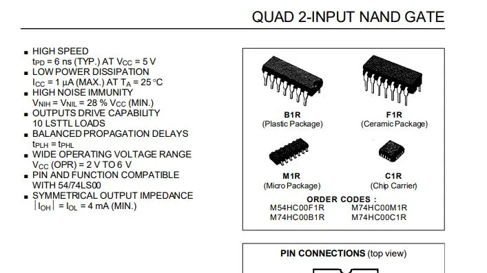
  • Form Factor: Available in various packages, including DIP (Dual In-line Package), SOIC (Small Outline Integrated Circuit), and QFP (Quad Flat Package), enabling easy integration into different types of PCBs (Printed Circuit Boards).

Key Characteristics

  • Power Consumption: Known for their low power consumption, especially in static states, making them ideal for battery-powered devices.
  • Operating Speed: Capable of operating at high frequencies, making them suitable for high-speed applications.
  • Operating Voltage: Typically operate within voltages between 1.8V and 5V, with some variants supporting lower or higher voltages.
  • Integration Density: Allow the integration of a large number of transistors on a single chip, facilitating the creation of complex circuits.
  • Noise Resistance: Highly immune to noise and interference, improving the reliability of circuits.

Typical Applications

  • Processors and Microcontrollers: Used in central processing units (CPUs) and microcontrollers due to their energy efficiency and high integration capability.
  • Memory Devices: Found in memory chips, including RAM and ROM, thanks to their high integration density and low energy consumption.
  • Mobile Devices: Essential in smartphones, tablets, and wearables, where energy efficiency is crucial.
  • Industrial Equipment: Employed in various industrial systems, including process control and automation, due to their robustness and reliability.
  • Consumer Electronics: Widely used in a variety of consumer electronic products, such as televisions, digital cameras, and audio systems.

Advantages

  • Energy Efficiency: They offer low power consumption, particularly in low-activity states.
  • High Integration: Enable the creation of highly complex circuits on a single chip.
  • Low Cost: Benefit from highly mature manufacturing processes, resulting in low production costs.
  • High Reliability: Resistant to noise with a low failure rate, making them highly reliable for various applications.

Disadvantages

  • Sensitivity to ESD: They can be sensitive to electrostatic discharge (ESD), requiring careful handling during manufacturing and assembly.
  • Performance at High Temperatures: Performance may be affected at very high temperatures, requiring proper thermal management.

FAQ:

  1. What are CMOS integrated circuits, and why are they important? CMOS integrated circuits are key to modern electronics due to their low power consumption, high density, and ability to integrate complex circuits on a single chip. They’re used in a wide range of applications, from mobile devices to industrial systems.
  2. What are the typical applications of CMOS circuits? CMOS circuits are used in processors, memory devices, mobile devices, industrial equipment, and consumer electronics due to their efficiency, small size, and high reliability.
  3. What are the key advantages of CMOS technology? CMOS technology offers energy efficiency, high integration density, low cost, and high reliability, making it ideal for a broad range of electronic applications.
  4. What are the disadvantages of CMOS circuits? CMOS circuits are sensitive to electrostatic discharge (ESD) and may have reduced performance in high-temperature environments, requiring appropriate handling and thermal management.
  5. How are CMOS integrated circuits used in processors and memory? CMOS circuits are extensively used in processors and microcontrollers because they allow for the integration of complex functionality while consuming minimal power, making them ideal for these high-performance applications.
CIDescriptionPins
40002 three-input NOR gates + 1 inverter14
40014 two-input NOR gates14
40022 four-input NOR gates14
40096 inverting buffers16
40106 non-inverting buffers16
40114 two-input NAND gates14
40132 D-type flip-flops14
40194 selectable AND/OR gates16
402014-stage binary counter/divider16
4026Decade counter with 7-segment decoder16
40304 two-input XOR gates14
40343-stage 8-bit bidirectional shift register24
40354-bit parallel shift register16
404012-stage binary counter with carry16
40414 buffers with original and complementary output14
40424 clocked D-type latches16
40434 three-stage latches16
4046PLL (Phase-Locked Loop)16
4047Low-power astable/monostable multivibrator14
40488 programmable/expandable 3-state gates16
40496 inverting buffers16
40506 non-inverting buffers16
40518-channel analog multiplexer/demultiplexer16
40524-channel dual analog multiplexer/demultiplexer16
406014-stage binary counter with ripple, carry, and oscillator16
40664 bilateral switches14
40696 inverters14
40704 XOR gates14
40722 four-input OR gates14
40733 three-input AND gates14
40764 three-stage register outputs16
40774 XNOR gates14
40814 two-input AND gates14
40894-bit binary multiplier14
40934 two-input NAND gates Schmitt Trigger16
40948-stage shift register and memory16
40998-bit addressable latch16
401066 Schmitt Trigger inverters14
401604-bit synchronous decade counter with asynchronous reset16
401614-bit synchronous binary counter with asynchronous reset16
401624-bit synchronous decade counter with synchronous reset16
401634-bit synchronous binary counter with synchronous reset16
401934-bit Up/Down binary counter16
45036 three-state buffers16
4510BCD Up/Down counter16
4511BCD to 7-segment decoder16
45128-input multiplexer with 3-stage output16
451416-to-1 decoder/demultiplexer with latch inputs24
4516Up/Down binary counter16
45194 two-input multiplexers16
45202 binary counters16
45282 monostable multivibrators16
4529Analog data selector 2 of 4 channels or 1 of 8 channels16
45382 precision monostable multivibrators16
4541Programmable timer14

CMOS Integrated Circuits Read More »

capacitor ceramico

Ceramic capacitors are widely used passive electronic components that store and release electrical energy. Known for their excellent electrical characteristics, compact size, and high performance in various applications, these capacitors are an essential part of modern electronic devices. Below are the main features and applications of ceramic capacitors, adapted to the standards and terminology relevant to the United States and the United Kingdom.

Structure and Operation

  • Dielectric Material: Ceramic capacitors use ceramic as the dielectric material, providing a high dielectric constant, which contributes to their compact size and effectiveness.
  • Shape: Available in various shapes, including SMD (Surface-Mount Device) and radial, which allows for easy integration onto printed circuit boards (PCBs).

Key Characteristics

  • Capacitance: Ceramic capacitors are available in a wide range of capacitances, from a few picofarads (pF) up to hundreds of microfarads (µF).
  • Tolerance: The tolerance generally ranges from ±1% to ±10%, providing high precision for many applications.
  • Rated Voltage: These capacitors can operate at different voltages, typically from 10V to 500V, with options available for even higher voltages.
  • Operating Temperature: The operational temperature range is typically from -55°C to +125°C, with some variants capable of withstanding even more extreme temperatures.
  • Stability: Ceramic capacitors exhibit excellent thermal stability and resistance to humidity variations, maintaining their electrical properties over time.

Typical Applications

  • Decoupling: Used for decoupling circuits, helping to stabilize voltage and reduce unwanted noise.
  • Signal Filtering: Employed in high-frequency filters due to their low Equivalent Series Resistance (ESR) and low dielectric losses.
  • Oscillators: Utilized in oscillator circuits because of their ability to maintain a stable capacitance value.
  • High-Frequency Circuits: Ideal for high-frequency applications where low ESR and excellent high-frequency performance are crucial.

Advantages

  • High Capacitance in Small Volume: These capacitors offer high capacitance in a compact size, making them ideal for modern, space-constrained devices.
  • Low Inductance: Especially useful in high-frequency applications due to their low inductance, ensuring better performance.
  • Cost: Ceramic capacitors are typically economical and widely available, making them a popular choice for various applications.

Disadvantages

  • Capacitance Variation with Temperature: Some classes of ceramic capacitors, especially Class II and III, may experience significant capacitance variation with temperature changes.
  • Microphonics: In certain applications, ceramic capacitors may exhibit microphonics, where mechanical vibrations translate into electrical variations, leading to potential performance issues.

Frequently Asked Questions (FAQ)

1. What is the difference between Class I, II, and III ceramic capacitors?

  • Class I capacitors have the most stable temperature and voltage characteristics but lower capacitance. They are ideal for precision applications.
  • Class II and III capacitors provide higher capacitance but exhibit more significant capacitance variation with temperature. They are often used where cost and size are more important than precision.

2. Can ceramic capacitors be used in high-frequency circuits?

Yes, ceramic capacitors are ideal for high-frequency applications due to their low ESR and inductance, which make them effective at filtering high-frequency signals.

3. Why do ceramic capacitors sometimes experience microphonics?

Microphonics can occur in ceramic capacitors because mechanical vibrations can induce electrical noise. This can be an issue in sensitive audio or high-precision circuits.

4. What is the typical lifespan of a ceramic capacitor?

Ceramic capacitors typically have a long lifespan when used within their specified voltage and temperature ranges. However, their performance may degrade if exposed to extreme conditions for prolonged periods.

If you liked this article, consider sharing it on social media, this will help to spread knowledge, leave your comment below so we can know your opinion.

Description of Values in Picofarads (pF) / Nanofarads (nF)Equivalent Codes
Ceramic Disc Capacitor 1pF x 50V-
Ceramic Disc Capacitor 1,2pF x 50V-
Ceramic Disc Capacitor 1,5pF x 50V-
Ceramic Disc Capacitor1,8pF x 50V-
Ceramic Disc Capacitor 2,2pF x 50V-
Ceramic Disc Capacitor 2,7pF x 50V-
Ceramic Disc Capacitor 3pF x 50V-
Ceramic Disc Capacitor 3,3pF x 50V-
Ceramic Disc Capacitor 3,9pF x 50V-
Ceramic Disc Capacitor 4,7pF x 50V-
Ceramic Disc Capacitor 5,6pF x 50V-
Ceramic Disc Capacitor 6,8pF x 50V-
Ceramic Disc Capacitor 7pF x 50V-
Ceramic Disc Capacitor 10pF x 50V-
Ceramic Disc Capacitor 12pF x 50V-
Ceramic Disc Capacitor 13pF x 50V-
Ceramic Disc Capacitor 15pF x 50V-
Ceramic Disc Capacitor 18pF x 50V-
Ceramic Disc Capacitor 22pF x 50V-
Ceramic Disc Capacitor 27pF x 50V-
Ceramic Disc Capacitor 33pF x 50V-
Ceramic Disc Capacitor 39pF x 50V-
Ceramic Disc Capacitor 47pF x 50V-
Ceramic Disc Capacitor 56pF x 50V-
Ceramic Disc Capacitor 68pF x 50V-
Ceramic Disc Capacitor 82pF x 50V-
Ceramic Disc Capacitor 100pF x 50V101
Ceramic Disc Capacitor 120pF x 50V121
Ceramic Disc Capacitor 150pF x 50V151
Ceramic Disc Capacitor 180pF x 50V181
Ceramic Disc Capacitor 220pF x 50V221
Ceramic Disc Capacitor 270pF x 50V271
Ceramic Disc Capacitor 330pF x 50V331
Ceramic Disc Capacitor 390pF x 50V391
Ceramic Disc Capacitor 470pF x 50V471
Ceramic Disc Capacitor 560pF x 50V561
Ceramic Disc Capacitor 680pF x 50V681
Ceramic Disc Capacitor 820pF x 50V821
Ceramic Disc Capacitor 1nF x 50V(0,001uF/1KpF/102)
Ceramic Disc Capacitor 1,2nF x 50V(1K2/1,2KpF/122/1n2K)
Ceramic Disc Capacitor 1,5nF x 50V(1K5/1,5KpF/152)
Ceramic Disc Capacitor 1,8nF x 50V(1K8/1,8KpF/182)
Ceramic Disc Capacitor 2,2nF x 50V(2K2/2,2KpF/222)
Ceramic Disc Capacitor 2,7nF x 50V(2K7/2,7KpF/272)
Ceramic Disc Capacitor 3,3nF x 50V(3K3/3,3KpF/332)
Ceramic Disc Capacitor 3,9nF x 50V(3K9/3,9KpF/392)
Ceramic Disc Capacitor 4,7nF x 50V(4K7/4,7KpF/472)
Ceramic Disc Capacitor 5,6nF x 50V(5K6/5,6KpF/562)
Ceramic Disc Capacitor 6,2nF x 50V(6K2/6,2KpF/622)
Ceramic Disc Capacitor 6,8nF x 50V(6K8/6,8KpF/682)
Ceramic Disc Capacitor 7,2nF x 50V(7K2/7,2KpF/722)
Ceramic Disc Capacitor 10nF x 50V(0,01uF/10K/10KpF/103)
Ceramic Disc Capacitor 15nF x 50V(0,015uF/15K/15KpF/153)
Ceramic Disc Capacitor 22nF x 50V(0,022uF/22K/22KpF/223)
Ceramic Disc Capacitor 27nF x 50V(0,027uF/27K/27KpF/273)
Ceramic Disc Capacitor 33nF x 50V(0,033uF/33K/33KpF/333)
Ceramic Disc Capacitor 39nF x 50V(0,039uF/39K/39KpF/393)
Ceramic Disc Capacitor 47nF x 50V(0,047uF/47K/47KpF/473)
Ceramic Disc Capacitor 56nF x 50V(0,056uF/56K/56KpF/563)
Ceramic Disc Capacitor 68nF x 50V(0,068uF/68KpF/683)
Ceramic Disc Capacitor 82nF x 50V(0,082uF/82K/82KpF/823)
Ceramic Disc Capacitor 100nF x 50V(0,1uF/100K/100Kpf/104)
Ceramic Disc Capacitor 220nF x 25V(0,22uF/220K/220KpF/224)

Commercial Value Table – Ceramic Capacitors Read More »

Transistor BD

BD series transistors are renowned for their ability to handle medium to high power, making them a staple in applications requiring robust current and voltage control. This article delves into the BDxxx transistor series, highlighting their characteristics, typical applications, and providing a detailed specification table.

Introduction to BD Series Transistors

BD series transistors are designed to handle higher currents and voltages compared to other series like BC. They find use in various applications, such as power amplifiers, voltage regulators, and switching circuits. Their robustness and reliability make them a popular choice in projects requiring consistent performance under demanding conditions.

BD Series Transistor Specifications

Below is a table summarizing the main BD series transistor codes, along with their specifications and typical applications:

CodeTypeVceo (V)Ic (A)Ptot (W)hFETypical Applications
BD135NPN451.512.540-250Power Amplifiers, Drivers
BD136PNP451.512.540-250Power Amplifiers, Drivers
BD137NPN601.512.540-250Power Amplifiers, Drivers
BD138PNP601.512.540-250Power Amplifiers, Drivers
BD139NPN801.512.540-250Audio Amplifiers, Regulators
BD140PNP801.512.540-250Audio Amplifiers, Regulators
BD175NPN6044015-75Voltage Regulators, Amplifiers
BD176PNP6044015-75Voltage Regulators, Amplifiers
BD243NPN10066520-100High-Power Audio Amplifiers
BD244PNP10066520-100High-Power Audio Amplifiers

Column Explanation

  • Code: The transistor identification within the BD series.
  • Type: Indicates whether the transistor is NPN or PNP.
  • Vceo (V): Maximum voltage between collector and emitter.
  • Ic (A): Maximum collector current.
  • Ptot (W): Maximum power dissipation.
  • hFE: Current gain (beta factor).
  • Typical Applications: Common use cases for the transistor.

Detailed Overview of Key BD Series Transistors

BD135, BD136, BD137, BD138

  • Type: NPN (BD135, BD137) and PNP (BD136, BD138).
  • Applications: Ideal for power amplifiers and drivers.
  • Characteristics:
    • BD135/BD136: Operates up to 45V; suitable for circuits with moderate voltage requirements.
    • BD137/BD138: Operates up to 60V; used in higher voltage applications, such as motor drivers.

BD139, BD140

  • Type: NPN (BD139) and PNP (BD140).
  • Applications: Frequently used in audio amplifiers and voltage regulators.
  • Characteristics:
    • BD139: Handles up to 80V; common in medium-power audio amplification.
    • BD140: Complementary to BD139, ideal for complementary pair configurations.

BD175, BD176

  • Type: NPN (BD175) and PNP (BD176).
  • Applications: Preferred in voltage regulators and high-current amplifiers.
  • Characteristics: Can handle up to 4A of current and dissipate 40W of power.

BD243, BD244

  • Type: NPN (BD243) and PNP (BD244).
  • Applications: High-power audio amplifiers requiring up to 6A and 100V.
  • Characteristics: Frequently used in high-performance audio systems.

Common Applications of BD Series Transistors

1. Power Amplifiers

BD135, BD136, BD137, and BD138 are widely used in power amplifiers due to their ability to manage higher currents and voltages, making them ideal for amplifier output stages.

2. Voltage Regulators

BD139, BD140, BD175, and BD176 are preferred in voltage regulation circuits, ensuring stable voltage output for precision applications.

3. High-Current Drivers

Transistors like BD243 and BD244 excel in driving high-current devices such as motors and large loads without performance degradation.

4. Audio Amplification

BD139, BD140, BD243, and BD244 are staples in high-power audio amplification, ensuring excellent sound quality and output power.

5. Prototyping and Educational Projects

The robustness and accessibility of BD transistors make them ideal for learning and experimentation in medium- to high-power circuit designs.

Conclusion

BDxxx transistors are versatile and reliable components, well-suited for a variety of electronic applications. Whether in power amplifiers, voltage regulators, high-current drivers, or audio systems, these transistors deliver consistent performance. Their role in electronic design remains pivotal, especially in medium to high-power scenarios.

FAQ

What are BD series transistors typically used for?
They are used in applications like power amplifiers, voltage regulators, audio systems, and high-current drivers.

What is the difference between BD139 and BD140?
BD139 is an NPN transistor, while BD140 is its PNP complement, often used together in complementary configurations.

Can BD series transistors handle high currents?
Yes, certain models like BD243 and BD244 can handle currents up to 6A.

Are BD series transistors suitable for audio applications?
Absolutely, BD139, BD140, BD243, and BD244 are frequently used in high-power audio amplification.

BDxxx Transistors: A Comprehensive Guide Read More »

Capacitores de Polister

Polyester capacitors are passive electronic components used to store and release electrical energy. They are widely recognized for their reliability, durability, and cost-effectiveness. Below is a detailed overview of their structure, key features, applications, advantages, and commercial values.

Structure and Operation

  • Dielectric Material: Polyester capacitors use a polyester film layer as the dielectric, sandwiched between two conductive layers, typically aluminum.
  • Form Factor: Commonly available in radial or axial formats, they are easy to mount on printed circuit boards (PCBs).

Key Features

  1. Capacitance: Available in a wide range, from a few picofarads (pF) to hundreds of nanofarads (nF) or even microfarads (µF).
  2. Tolerance: Typically ±5% to ±10%, providing sufficient precision for general-purpose applications.
  3. Rated Voltage: Operates at voltages ranging from 50V to 250V, with higher-voltage versions also available.
  4. Operating Temperature: Functions within a temperature range of -55°C to +125°C, suitable for diverse environmental conditions.
  5. Stability: Offers excellent thermal stability and resistance to humidity, maintaining electrical properties over time.

Typical Applications

  • Decoupling Circuits: Stabilizes voltage and reduces unwanted noise in circuits.
  • Signal Filtering: Used in high-frequency filters due to their stability and low inductance.
  • Oscillators: Ideal for oscillator circuits, maintaining a consistent capacitance.
  • High-Frequency Circuits: Performs well in high-frequency applications due to low Equivalent Series Resistance (ESR) and minimal dielectric loss.

Advantages

  • Cost-Effective: Economical and widely available.
  • Reliable: Long lifespan and dependable performance under varying conditions.
  • Versatile: Suitable for a wide range of electronic applications.

Disadvantages

  • High-Frequency Performance: While suitable for most high-frequency uses, they may not outperform ceramic or polypropylene capacitors in extreme frequencies.

Commercial Value Table

The table below presents common commercial values for polyester capacitors, including capacitance, equivalent codes, tolerances, rated voltage, operating temperature, and typical applications.

Nominal Value (nF)Nominal Value (µF)Nominal Value (pF)Equivalent CodeToleranceNominal Voltage (V)Operating TemperatureTypical Applications
1 nF0.001 µF1000 pF1KpF, 102±5%, ±10%50V, 100V, 250V-55°C to +125°CDecoupling circuits, filtering
1.2 nF0.0012 µF1200 pF1K2, 122, 1n2K±5%, ±10%50V, 100V, 250V-55°C to +125°COscillators, resonant circuits
1.5 nF0.0015 µF1500 pF1K5, 152±5%, ±10%50V, 100V, 250V-55°C to +125°CHigh-frequency filtering
1.8 nF0.0018 µF1800 pF1K8, 182±5%, ±10%50V, 100V, 250V-55°C to +125°CDecoupling circuits
2.2 nF0.0022 µF2200 pF2K2, 222±5%, ±10%50V, 100V, 250V-55°C to +125°CSignal filtering
2.7 nF0.0027 µF2700 pF2K7, 272±5%, ±10%50V, 100V, 250V-55°C to +125°COscillators
3.3 nF0.0033 µF3300 pF3K3, 332±5%, ±10%50V, 100V, 250V-55°C to +125°CDecoupling circuits
3.9 nF0.0039 µF3900 pF3K9, 392±5%, ±10%50V, 100V, 250V-55°C to +125°CHigh-frequency filtering
4.7 nF0.0047 µF4700 pF4K7, 472±5%, ±10%50V, 100V, 250V-55°C to +125°CDecoupling circuits
5.6 nF0.0056 µF5600 pF5K6, 562±5%, ±10%50V, 100V, 250V-55°C to +125°CSignal filtering
6.2 nF0.0062 µF6200 pF6K2, 622±5%, ±10%50V, 100V, 250V-55°C to +125°COscillators
6.8 nF0.0068 µF6800 pF6K8, 682±5%, ±10%50V, 100V, 250V-55°C to +125°CDecoupling circuits
7.2 nF0.0072 µF7200 pF7K2, 722±5%, ±10%50V, 100V, 250V-55°C to +125°CHigh-frequency filtering
8.2 nF0.0082 µF8200 pF8K2, 822±5%, ±10%50V, 100V, 250V-55°C to +125°CDecoupling circuits
10 nF0.01 µF10000 pF10K, 10KpF, 103±5%, ±10%50V, 100V, 250V-55°C to +125°CSignal filtering
15 nF0.015 µF15000 pF15K, 15KpF, 153±5%, ±10%50V, 100V, 250V-55°C to +125°COscillators
22 nF0.022 µF22000 pF22K, 22KpF, 223±5%, ±10%50V, 100V, 250V-55°C to +125°CDecoupling circuits
27 nF0.027 µF27000 pF27K, 27KpF, 273±5%, ±10%50V, 100V, 250V-55°C to +125°CHigh-frequency filtering
33 nF0.033 µF33000 pF33K, 33KpF, 333±5%, ±10%50V, 100V, 250V-55°C to +125°COscillators
39 nF0.039 µF39000 pF39K, 39KpF, 393±5%, ±10%50V, 100V, 250V-55°C to +125°CDecoupling circuits
47 nF0.047 µF47000 pF47K, 47KpF, 473±5%, ±10%50V, 100V, 250V-55°C to +125°CSignal filtering
56 nF0.056 µF56000 pF56K, 56KpF, 563±5%, ±10%50V, 100V, 250V-55°C to +125°COscillators
68 nF0.068 µF68000 pF68KpF, 683±5%, ±10%50V, 100V, 250V-55°C to +125°CDecoupling circuits
82 nF0.082 µF82000 pF82K, 82KpF, 823±5%, ±10%50V, 100V, 250V-55°C to +125°CHigh-frequency filtering
100 nF0.1 µF100000 pF100K, 100KpF, 104±5%, ±10%50V, 100V, 250V-55°C to +125°CDecoupling circuits
220 nF0.22 µF220000 pF220K, 220KpF, 224±5%, ±10%50V, 100V, 250V-55°C to +125°CSignal filtering
270 nF0.27 µF270000 pF270K, 270KpF, 274±5%, ±10%50V, 100V, 250V-55°C to +125°COscillators
330 nF0.33 µF330000 pF330K, 330KpF, 334±5%, ±10%50V, 100V, 250V-55°C to +125°CDecoupling circuits
390 nF0.39 µF390000 pF390K, 390KpF, 394±5%, ±10%50V, 100V, 250V-55°C to +125°CHigh-frequency filtering
470 nF0.47 µF470000 pF470K, 470KpF, 474±5%, ±10%50V, 100V, 250V-55°C to +125°CDecoupling circuits
560 nF0.56 µF560000 pF560K, 560KpF, 564±5%, ±10%50V, 100V, 250V-55°C to +125°CSignal filtering
680 nF0.68 µF680000 pF680K, 680KpF, 684±5%, ±10%50V, 100V, 250V-55°C to +125°COscillators

Additional Notes

  • Tolerance: Typically ranges from ±5% to ±10%.
  • Rated Voltage: Common ratings are 50V, 100V, and 250V, suitable for various applications.
  • Operating Temperature: -55°C to +125°C, enabling use in diverse environments.
  • Applications: Polyester capacitors are widely used in decoupling, signal filtering, oscillators, and high-frequency circuits due to their stability and low loss.

FAQ

1. What makes polyester capacitors suitable for general applications?
Polyester capacitors offer a balance of cost, reliability, and performance, making them ideal for general-purpose applications.

2. Can polyester capacitors be used in extreme temperature conditions?
Yes, they operate reliably within a wide temperature range of -55°C to +125°C.

3. Are polyester capacitors suitable for very high-frequency applications?
While they perform well at high frequencies, ceramic or polypropylene capacitors may be better for extreme high-frequency needs.

4. How do I choose the right tolerance for my circuit?
Choose a tighter tolerance (e.g., ±5%) for precision circuits and a wider tolerance (e.g., ±10%) for general-purpose applications.

Commercial Values Table – Polyester Capacitors Read More »

Transistor Série BCxxx

The BC series transistors are widely used in various electronic applications due to their versatility and reliable performance. This article provides a complete guide on the BCxxx transistors, exploring their features, applications, and detailed specifications. A comprehensive table with all BC series codes and their main characteristics is also included.

Introduction to BC Series Transistors

Transistors are fundamental electronic components that play crucial roles in amplification and switching circuits. The BC series is one of the most popular, including general-purpose NPN and PNP transistors designed for a wide range of applications. This versatility stems from their development based on fundamental electrical resistance laws laid out by pioneers like George Simon Ohm.

BC Series Transistor Table

Below is a table listing key BC series transistor codes, their characteristics, and typical applications:

CodeTypeVceo (V)Ic (A)Ptot (W)hFETypical Applications
BC107NPN450.10.3110-450Audio Amplification, Small Signals
BC108NPN200.10.3110-800Audio Amplification, Small Signals
BC109NPN200.10.3110-800Audio Amplification, Small Signals
BC177PNP450.10.3125-800Audio Amplification, Small Signals
BC178PNP200.10.3125-800Audio Amplification, Small Signals
BC179PNP200.10.3125-800Audio Amplification, Small Signals
BC546NPN650.10.5110-800Signal Amplification, Switching
BC547NPN450.10.5110-800Signal Amplification, Switching
BC548NPN300.10.5110-800Signal Amplification, Switching
BC549NPN300.10.5110-800Signal Amplification, Switching, Low Noise
BC556PNP650.10.5110-800Signal Amplification, Switching
BC557PNP450.10.5110-800Signal Amplification, Switching
BC558PNP300.10.5110-800Signal Amplification, Switching
BC559PNP300.10.5110-800Signal Amplification, Switching, Low Noise

Column Explanations

  • Code: Identification within the BC series.
  • Type: Indicates whether the transistor is NPN or PNP.
  • Vceo (V): Maximum collector-emitter voltage.
  • Ic (A): Maximum collector current.
  • Ptot (W): Maximum power dissipation.
  • hFE: Current gain (beta factor).
  • Typical Applications: Common uses for the transistor.

Detailed Analysis of Key BC Transistors

BC107, BC108, BC109 (NPN)

Applications: Ideal for audio and small signal amplification.

  • BC107: High robustness for audio signals, supports up to 45V.
  • BC108/BC109: Suitable for lower voltage applications (up to 20V).

BC177, BC178, BC179 (PNP)

Applications: Complementary to BC107, BC108, BC109; used in low-power audio circuits.

  • Features: Offer reliable performance for low-power projects requiring complementary NPN/PNP pairs.

BC546, BC547, BC548, BC549 (NPN)

Applications: Signal amplification and switching.

  • BC546: High voltage (65V), robust designs.
  • BC547: Balanced versatility and robustness.
  • BC548: Common for low-voltage applications.
  • BC549: Low-noise performance for sensitive circuits.

BC556, BC557, BC558, BC559 (PNP)

Applications: Complementary to BC546-BC549.

  • BC556: High voltage, ideal for robust circuits.
  • BC559: Low-noise applications, complements BC549.

Common Applications of BC Series Transistors

  1. Signal Amplification
    • Widely used in audio preamplifiers and low-noise circuits.
    • Preferred models: BC549, BC559.
  2. Switching
    • Suitable for small current switching tasks like LED control and relay activation.
    • Popular models: BC546, BC556.
  3. Audio Circuits
    • Common in consumer and hi-fi audio devices.
    • Preferred models: BC108, BC109.
  4. Prototyping and Education
    • Low cost and availability make them ideal for educational projects.

Conclusion

The BCxxx series transistors are versatile, reliable, and widely used in numerous electronic applications, from signal amplification to switching. Their availability and performance make them a staple for engineers and hobbyists alike.

FAQ

1. What does Vceo represent in BC transistors?
Vceo is the maximum voltage the transistor can handle between the collector and emitter when the base is open.

2. Can BC series transistors be used interchangeably?
In some cases, yes, but always verify the voltage, current, and power requirements.

3. What are complementary transistors?
These are PNP/NPN pairs designed to work together in push-pull configurations, common in amplifiers.

BCxxx Transistors Code: Comprehensive Guide and Applications Read More »

Below is a table showcasing normalized capacitor values based on the E12 series. These values are widely used in electronic circuit design and manufacturing for their practicality and standardization.

Nominal Value (μF)Tolerance (%)Maximum Voltage (V)
1.0±2050
1.2±2050
1.5±2050
1.8±2050
2.2±2050
2.7±2050
3.3±2050
3.9±2050
4.7±2050
5.6±2050
6.8±2050
8.2±2050
10±2050
12±2025, 35, 50, 63
15±2025, 35, 50, 63
18±2025, 35, 50, 63
22±2010, 16, 25, 35, 50, 63, 100
27±2010, 16, 25, 35, 50, 63, 100
33±2010, 16, 25, 35, 50, 63, 100
39±2010, 16, 25, 35, 50, 63, 100
47±2010, 16, 25, 35, 50, 63, 100
56±2010, 16, 25, 35, 50, 63, 100
68±2010, 16, 25, 35, 50, 63, 100
82±2010, 16, 25, 35, 50, 63, 100

Notes:

  1. Tolerance: The values above are based on the E12 series, offering a ±20% tolerance typically found in electrolytic capacitors.
  2. Voltage Ratings: The voltage column indicates the maximum safe operating voltage for the capacitor. Always verify the exact ratings for specific projects.
  3. Practical Usage: These values simplify component selection, making the E12 series ideal for general-purpose electronic design.

Importance of Choosing the Right Capacitor

Selecting capacitors with the correct value, tolerance, and voltage rating is crucial for ensuring circuit stability and reliability. Misjudging these factors can lead to operational failures or reduced efficiency in your electronic systems.

FAQ

1. What is the E12 series?
The E12 series is a standard set of 12 logarithmically spaced values per decade used for resistors and capacitors. These values simplify inventory management and design in electronics.

2. Why are capacitors classified by tolerance?
Capacitors are classified by tolerance to indicate how much their actual capacitance can deviate from the nominal value. For example, ±20% means the capacitance may vary 20% above or below the stated value.

3. Can I use a capacitor with a higher voltage rating than required?
Yes, using a capacitor with a higher voltage rating is safe and may enhance longevity. However, it can be more expensive and physically larger than needed.

4. What happens if I use the wrong capacitor value?
Using an incorrect value can cause circuit malfunction, affect timing or filtering properties, or even damage components.

Standard Capacitor Table: E12 Series Values Read More »

Scroll to Top