Calculation Spreadsheet for the Implementation of Photovoltaic Plants Read More »

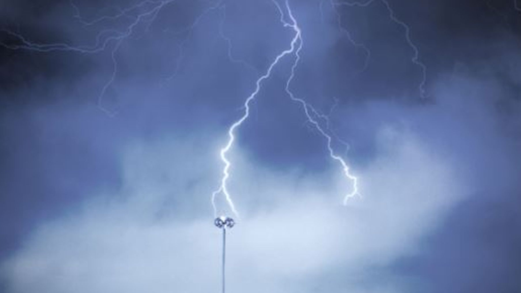
Lightning strikes represent a significant threat to buildings, power transmission lines, and electronic equipment. Implementing a robust Lightning Protection System (LPS) is essential to minimize damage caused by these events. In this article, we explore the components, methods, and best practices to ensure the safety of your installations.
Lightning strikes can be categorized as either direct or indirect:
An effective Lightning Protection System consists of several key elements, each playing a critical role in ensuring the safety of the structure:
In the United States, lightning protection standards such as NFPA 780 and UL 96A, and in the UK, standards like BS EN 62305, provide guidelines for LPS design. Common methods include:
The RSM determines protected areas using a conceptual “rolling sphere” to simulate the trajectory of a lightning strike.
Also known as the “traditional lightning rod method,” this approach simplifies protection for smaller structures.
This approach is based on Faraday’s principle, using a grid of conductors to protect large areas such as warehouses, factories, or skyscrapers.
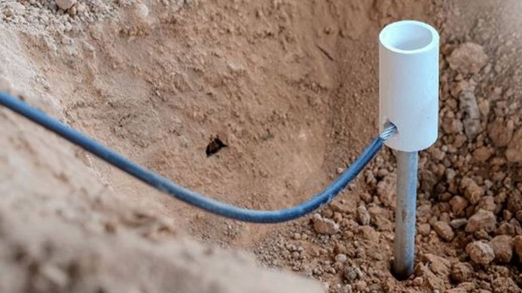
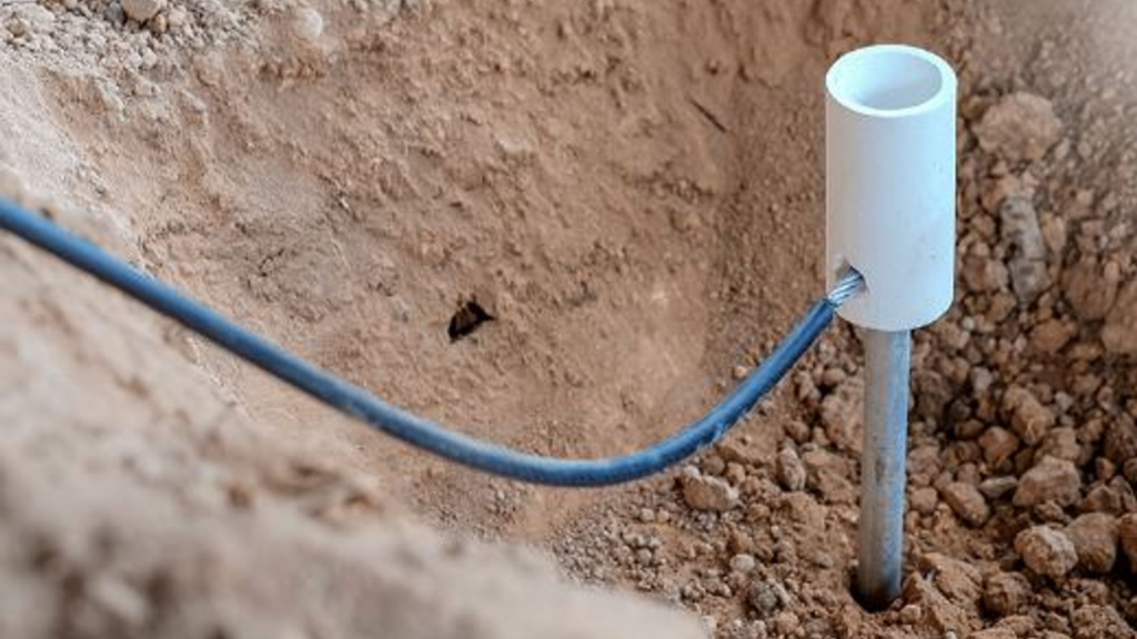
Grounding is a critical component of any LPS. According to NFPA 780 and BS EN 62305, the grounding resistance should ideally be below 10 ohms. Proper grounding ensures efficient dissipation of lightning energy, while regular testing of electrical continuity ensures all conductive elements function effectively in a lightning event.
Implementing a compliant and effective Lightning Protection System is essential to safeguard structures against lightning strikes. Adhering to standards like NFPA 780 or BS EN 62305 ensures both safety and compliance, minimizing risks and preserving the integrity of your assets.
If you liked this article, consider sharing it on social media, this will help to spread knowledge, leave your comment below so we can know your opinion.
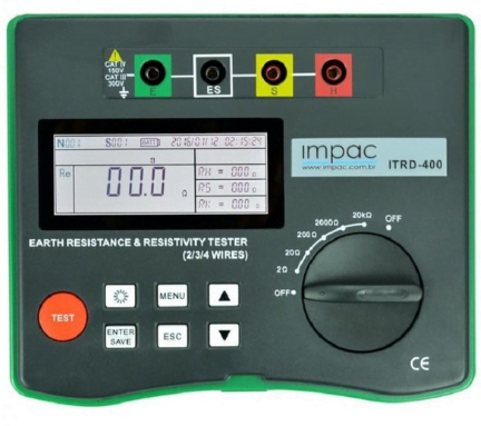
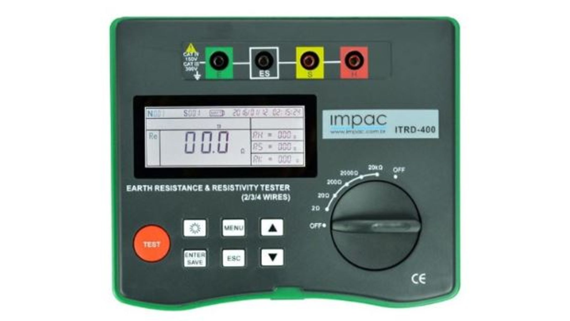
An Earth Resistance Tester is a crucial instrument used by engineers and technicians to measure soil resistance to electrical discharges. This measurement evaluates the efficiency of grounding systems, ensuring they function properly and provide safety for equipment and people.
Grounding is essential in electrical installations to prevent power surges or overloads from damaging equipment. When analyzing a grounding system, the impedance values of electrodes are assessed according to electrical codes and engineering standards.
The Earth Resistance Tester measures this impedance: the lower the impedance, the better the grounding performance. Ideally, grounding resistance should be below 10 Ohms, while values above 30 Ohms may pose risks.
Different applications and precision requirements dictate the type of tester to use. The main types include:
This traditional tester measures soil resistance by evaluating the voltage along the path of the electric current back to the grounding electrode. It is ideal for open systems and industrial environments.
This type measures resistance in closed circuits without disconnecting the ground system, making it practical and efficient for quick maintenance.
Advanced models offering precise measurements with features like data storage and graphical analysis.
Compact and lightweight, this tester is ideal for fieldwork requiring mobility.
Used for measuring resistance at higher frequencies, suitable for specific installations such as communication systems.
Type | Main Application | Notable Advantage |
|---|---|---|
Three-Wire Tester | Isolated systems | High accuracy in complex systems |
Clamp-On Tester | Maintenance and inspections | Measures without disconnection |
Digital Tester | Complex industrial installations | Advanced features |
Portable Tester | Field measurements | Compact and transportable |
High-Frequency Tester | SPDA and communication systems | Operates at high frequencies |
The Earth Resistance Tester is indispensable for ensuring electrical safety in residential, industrial, and commercial installations. Proper use and maintenance prevent equipment damage and enhance safety for people.
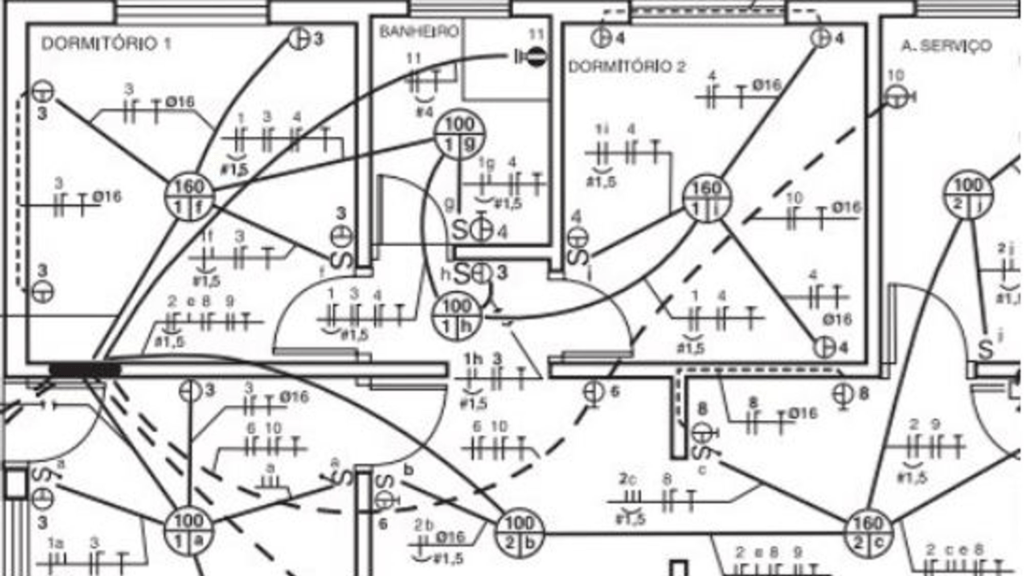
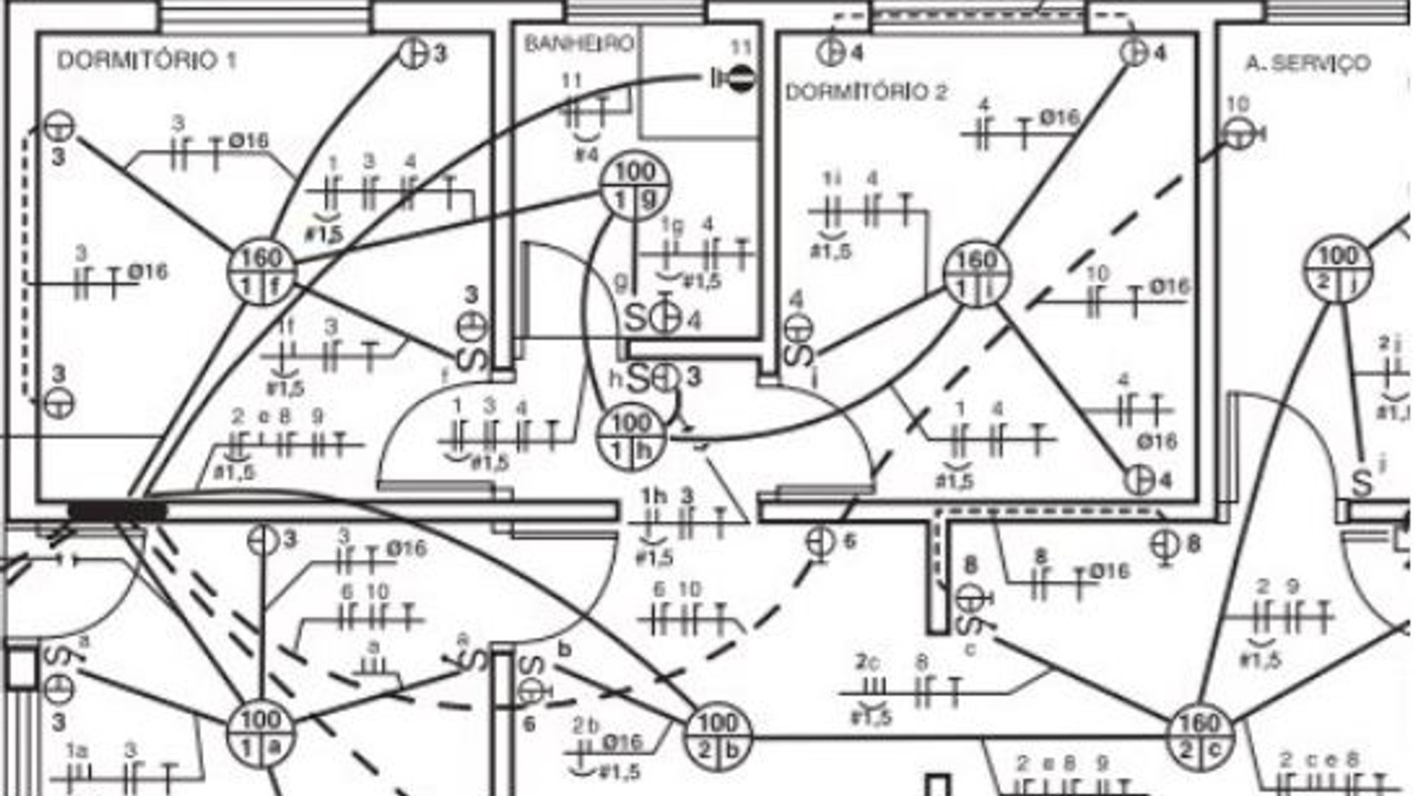
Creating electrical projects is a crucial process to ensure safety, efficiency, and compliance with regulations, especially when conducted according to current technical standards such as the National Electrical Code (NEC) in the United States and the BS 7671 (IET Wiring Regulations) in the United Kingdom. In this article, we will explore in detail each step of the process, from component sizing to voltage drop verification, ensuring you can design a robust electrical project that adheres to these regulations.
Well-designed electrical projects, in compliance with standards such as the NEC and BS 7671, are essential to prevent accidents, optimize energy use, and ensure installations meet regulatory requirements. Following these standards is critical for the safety and longevity of electrical systems.
The NEC and BS 7671 provide guidelines for the sizing and location of components, such as light points, outlets, distribution boards, switches, and doorbell buttons. These components must adhere to specific criteria to ensure safety and functionality. It is essential to position each component strategically, based on the intended use of spaces, ensuring efficient electrical distribution.
The design and installation of electrical conduit networks must be planned to safely and efficiently route electrical wires throughout environments. Careful planning of this network helps avoid issues such as overloads and facilitates future maintenance. The NEC and BS 7671 specify materials and installation methods to ensure the durability and safety of the system.
The distribution of electrical loads across separate circuits, such as lighting, outlets, and high-power equipment, is recommended by the NEC and BS 7671. This division enables balanced energy demand distribution, preventing overloads and enhancing system safety. The standards also set current limits for each circuit type, ensuring the system is properly sized.
The load panel and single-line diagram should be organized clearly and in detail, to facilitate system understanding and maintenance. The load panel must indicate all loads connected to the system, while the single-line diagram provides a graphical representation of the energy distribution.
The standards specify minimum conduit diameters and wire gauges based on the expected electrical current and installation conditions. Adhering to these specifications prevents issues like overheating and ensures system durability.
The NEC and BS 7671 set limits for the maximum allowable voltage drop in electrical circuits. Verifying the voltage drop is essential to ensure that all consumption points receive voltage within acceptable parameters. To do this, the standards recommend using minimum wire gauges, such as 1.5 mm² for lighting circuits and 2.5 mm² for outlet circuits, ensuring system compliance and safety.
The sizing of feeders should be done based on the total energy demand, considering voltage drop limits and the specifications in the NEC and BS 7671. The standards provide guidance on selecting conductors and sizing criteria to ensure that feeders meet safety and efficiency requirements.
The NEC and BS 7671 require that the main load panel be organized to separate loads by type, such as lighting, outlets, showers, air conditioning, and motors. This organization simplifies energy distribution management and ensures that each load type is powered correctly, in compliance with standard limits.
The diversity factor, as outlined in the NEC and BS 7671, is used to optimize the sizing of electrical systems, considering that not all loads will be used simultaneously. The standards provide guidelines on how to calculate the diversity factor for different types of buildings and installations, ensuring efficient electrical system sizing without overloading components.
The general service entrance should be sized based on total demand, considering NEC and BS 7671 specifications. This includes selecting the appropriate cabling, protective devices, and, if necessary, installing a substation.
1. Why is it important to follow the NEC and BS 7671 in electrical project design?
Following the NEC and BS 7671 is crucial to ensure the safety of electrical installations, prevent accidents, and ensure that the system complies with current regulations.
2. What are the NEC and BS 7671, and what do they cover?
The NEC (National Electrical Code) is a U.S. standard that governs electrical installations, while BS 7671 (IET Wiring Regulations) is the UK standard for wiring and electrical installations. Both standards cover guidelines from component sizing to safety and maintenance criteria.
3. How do the NEC and BS 7671 guide the sizing of electrical components?
Both standards provide specific criteria for sizing and positioning components, such as conduits, wiring, and distribution boards, ensuring the safety and efficiency of installations.
4. What are the voltage drop limits established by the NEC and BS 7671?
The NEC allows a maximum voltage drop of 3% for branch circuits and feeders, while BS 7671 recommends a maximum drop of 4% for circuits in normal installations, ensuring that voltage at consumption points remains within proper limits.
5. How do the NEC and BS 7671 address the diversity factor in electrical system sizing?
Both standards offer guidance on calculating the diversity factor, which helps optimize electrical system sizing by considering the non-simultaneous use of loads, ensuring efficiency and safety.
If you liked this article, consider sharing it on social media, this will help to spread knowledge, leave your comment below so we can know your opinion.
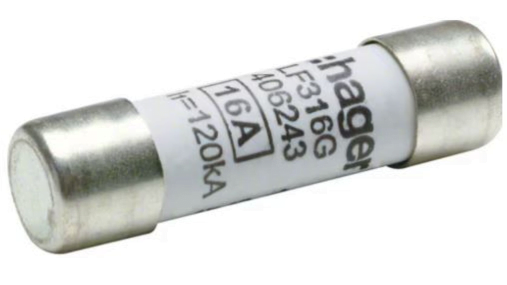
The table of Rated Current for Cylindrical Fuses and Bases provides information on the current capacities of cylindrical fuses, which are critical components in electrical systems for protection against overcurrents.
| Cylindrical Fuses Utilization Category gG/aM | |||||
|---|---|---|---|---|---|
| Dim. (mm) | Rated Current (A) | Dim. (mm) | Rated Current (A) | Dim. (mm) | Rated Current (A) |
| 10x38 | 1 | 14x51 | 2 | 22x58 | 8 |
| 10x38 | 2 | 14x51 | 4 | 22x58 | 10 |
| 10x38 | 4 | 14x51 | 6 | 22x58 | 12 |
| 10x38 | 6 | 14x51 | 8 | 22x58 | 16 |
| 10x38 | 8 | 14x51 | 10 | 22x58 | 20 |
| 10x38 | 10 | 14x51 | 12 | 22x58 | 25 |
| 10x38 | 12 | 14x51 | 16 | 22x58 | 32 |
| 10x38 | 16 | 14x51 | 20 | 22x58 | 40 |
| 10x38 | 20 | 14x51 | 25 | 22x58 | 50 |
| 10x38 | 25 | 14x51 | 32 | 22x58 | 63 |
| 10x38 | 32 | 14x51 | 40 | 22x58 | 80 |
| 14x51 | 50 | 22x58 | 100 | ||
| Bases for Cylindrical Fuses | |||
|---|---|---|---|
| Dim. (mm) | Rated Current (A) | Number of Poles | Conductor Cross-Section (mm²) |
| 10x38 | 32 | 1 | 2,5 a 16 |
| 10x38 | 32 | 2 | 2,5 a 16 |
| 10x38 | 32 | 3 | 2,5 a 16 |
| 10x38 | 32 | 3+N | 2,5 a 16 |
| 14X51 | 50 | 1 | 2,5 a 25 |
| 14X51 | 50 | 2 | 2,5 a 25 |
| 14X51 | 50 | 3 | 2,5 a 25 |
| 14X51 | 50 | 3+N | 2,5 a 25 |
| 22x58 | 100 | 1 | 4 a 50 |
| 22x58 | 100 | 2 | 4 a 50 |
| 22x58 | 100 | 3 | 4 a 50 |
| 22x58 | 100 | 3+N | 4 a 50 |
If you enjoyed this article, consider sharing it on social media. By doing so, you’ll help spread knowledge. Leave your comment below to let us know your opinion.

The power factor (PF) is a crucial concept in electrical systems, representing the relationship between active power, which performs useful work, and apparent power, which is the vector combination of active and reactive power. Understanding and managing power factor is essential for optimizing the efficiency of electrical systems and avoiding issues such as energy losses and conductor overheating.
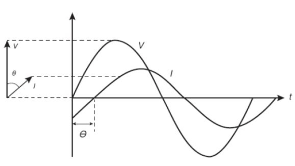
Power factor is defined as the cosine of the phase angle between current and voltage in a circuit. For single-phase AC circuits, it can be calculated using the formula:
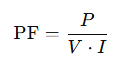
Where:
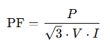
For three-phase systems, the formula is adjusted to consider the three phases:
The power factor value ranges from 0 to 1 (or 0% to 100% in percentage terms), where:
Electrical systems deal with three main types of power:
These powers are represented in a power triangle, where the power factor is the cosine of the phase angle.
Consider a three-phase motor operating at 220 volts, drawing 25 amperes per phase with a power factor of 80%. The power supplied by the system can be calculated as:

This calculation illustrates how power factor directly affects the total power required by the system.
A low power factor, typically below 0.92, can lead to several issues in an electrical installation, including:
To correct power factor, capacitors are commonly installed in parallel with inductive loads. This reduces reactive power, increases power factor, and improves system efficiency.
Managing power factor is vital for electrical engineers aiming to optimize energy efficiency. A high power factor not only reduces operating costs but also extends equipment lifespan and enhances system stability. Therefore, power factor should be a key consideration in electrical design, maintenance, and operation of installations.
1. What is power factor?
Power factor (PF) is a measure of how efficiently electrical power is used. It is defined as the ratio of active power (used for useful work) to apparent power (total power supplied to the system).
2. What is the difference between active, reactive, and apparent power?
3. What causes a low power factor?
A low power factor is usually caused by inductive loads such as motors, transformers, and reactors, which require reactive power to create magnetic fields necessary for their operation.
4. What are the consequences of a low power factor?
5. How can power factor be corrected?
Power factor correction is typically achieved by installing capacitors parallel to inductive loads. Capacitors provide reactive power locally, reducing the demand on the power supply and improving efficiency.
6. What is the ideal power factor?
An ideal power factor is close to 1 (or 100%), indicating that all supplied power is being effectively used for productive work.
7. Why do utility companies charge penalties for low power factor?
Utilities charge penalties because a low power factor increases the current in the system, requiring larger infrastructure and causing greater energy losses.
8. What is the difference between individual and centralized power factor correction?
9. What equipment can help monitor power factor?
Power meters with PF monitoring, protection relays, and SCADA (Supervisory Control and Data Acquisition) systems are commonly used to track and manage power factor.
10. Does power factor affect the lifespan of equipment?
Yes, a low power factor can cause overloading and heating of equipment, leading to reduced lifespan and potential failures.
11. How do capacitors improve power factor?
Capacitors counteract the inductive effects of loads by supplying reactive power locally, reducing the overall reactive power demand on the system and improving the power factor.
12. What is a power factor penalty, and how is it calculated?
A power factor penalty is a surcharge imposed by utility companies when the power factor falls below a certain threshold, typically 0.92 or 0.95. The penalty is calculated based on the additional apparent power required due to the inefficiency.
13. How does power factor impact energy costs?
A low power factor results in higher apparent power demand, increasing the utility’s delivery capacity and operational costs, which are often passed on to consumers through penalties or higher rates.
14. Can renewable energy systems impact power factor?
Yes, systems like solar inverters or wind turbines may influence power factor, especially if not properly designed or synchronized with the grid. Advanced inverters with power factor correction capabilities can mitigate these effects.
15. Is power factor important for residential installations?
While power factor is more critical in industrial and commercial settings, improving it in residential systems can still help reduce energy waste and optimize the performance of household appliances.
If you liked this article, consider sharing it on social media, this will help to spread knowledge, leave your comment below so we can know your opinion.
Grounding is an essential part of electrical installations, ensuring a safe connection between electrical structures or systems and the earth. This connection allows various types of electrical currents to safely flow into the ground, minimizing risks to people, animals, and equipment. The main currents dissipated to the ground include:
In the United States and the United Kingdom, grounding systems for low voltage installations follow stringent standards:
A low-voltage grounding system comprises the following components:
In industrial and commercial settings, integrating various grounding subsystems enhances performance and safety. Key considerations include:
Electrical systems are classified using codes (e.g., TN, TT, IT), which dictate the grounding method and protective measures:
To ensure effective fault protection, the impedance of the fault current path (Zs) and the operating current of the protective device (Ia) must meet the condition:
Zs × Ia ≤ U0, where U0 is the nominal phase-to-ground voltage.
This guarantees the protective device (e.g., a circuit breaker) will disconnect the circuit within the specified time, minimizing exposure to dangerous touch voltages.
Grounding standards, such as NEC and BS 7671, classify risk based on environmental conditions and human electrical resistance. This determines additional protective measures required for specific scenarios, like wet environments or medical facilities.
Grounding is a cornerstone of electrical safety. Understanding grounding schemes, impedance considerations, and risk classifications is critical for designing and maintaining safe electrical systems. Compliance with standards such as NEC and BS 7671 ensures installations are safe, efficient, and free from electrical hazards.
If you liked this article, consider sharing it on social media, this will help to spread knowledge, leave your comment below so we can know your opinion.


To develop efficient lighting projects, understanding the fundamental lighting quantities is essential. These quantities are based on definitions established by standards such as ISO 8995-1 and by organizations like the Illuminating Engineering Society (IES) in the United States and the British Standards Institution (BSI) in the United Kingdom. Below, we explore the key concepts governing light and its application in lighting design.
Light is the portion of radiant energy visible to the human eye, perceived through the stimulation of the retina. The electromagnetic radiation detectable by the human eye spans wavelengths from 380 to 760 nanometers (nm). A nanometer equals one billionth of a meter.
The wavelength (λ) is the distance between corresponding points of consecutive waves, usually peaks, in a graph of space versus amplitude. The product of wavelength and frequency (f) equals the speed of light (c), which is constant at approximately 186,282 miles per second (or 3 × 10⁸ m/s).
The color of light is determined by its wavelength. Violet light has the shortest visible wavelength (380–450 nm), while red light has the longest (640–760 nm). The visible spectrum, illustrated below, shows that yellow light at 555 nm provides the greatest visual sensitivity.
Luminous intensity measures the amount of light emitted by a source in a specific direction. It is defined as the luminous intensity, perpendicular to a flat surface of 1/600,000 square meters of a black body at the temperature of platinum’s freezing point, under 1 atmospheric pressure.
This measure is critical for directional lighting, such as spotlights and reflectors, where intensity in a specific direction is prioritized over general lighting.
Luminous flux represents the total amount of light emitted by a source in all directions. It is defined as the light flux emitted within a solid angle of one steradian by a source of one candela.
In practice, luminous flux helps determine the “amount” of light produced by a lamp or fixture, regardless of direction. For example, when comparing different lighting technologies, luminous flux (measured in lumens) provides insight into how much light each type of lamp generates.
Illuminance, formerly called illuminance, measures the amount of luminous flux incident on a surface. It is calculated by dividing luminous flux (in lumens) by the area of the surface (in square meters). One lux equals the illuminance on a one-square-meter surface receiving one lumen.
This quantity is vital for determining suitable lighting levels for environments such as offices, homes, or public spaces. Different activities require different levels of illuminance; for instance, a reading room requires higher lux levels than a corridor.
Luminance measures the amount of light emitted or reflected by a surface in a specific direction, expressed in candelas per square meter (cd/m²), or nit. It describes the apparent brightness of a surface to the human eye.
For example, a TV or computer monitor is characterized by luminance, which determines how bright the image appears to the viewer.
Luminous efficacy is the ratio of luminous flux emitted by a lamp to the electrical power consumed, expressed in lumens per watt (lm/W).
Higher luminous efficacy means more light is produced per watt of energy consumed, which is crucial for energy-efficient lighting designs. LEDs, for instance, offer high luminous efficacy, making them an energy-efficient choice compared to traditional incandescent bulbs.
The light distribution curve is a diagram illustrating how a fixture’s luminous intensity is distributed in different directions. Typically presented as a polar diagram, it shows intensities as a function of the angle formed with the vertical.
This diagram is essential for optimizing lighting placement and ensuring targeted illumination, such as in streetlights or floodlights.
Understanding these quantities is fundamental in lighting design practice, enabling precise calculations and efficient illumination planning. From selecting light fixtures to determining their placement, every decision affects visual comfort and energy consumption.
1. What is wavelength, and how does it affect the color of light?
Wavelength is the distance between corresponding points on consecutive light waves. It determines the color of light, with shorter wavelengths producing violet light and longer wavelengths producing red light.
2. What is the difference between luminous intensity and luminous flux?
Luminous intensity (measured in candela) is the light emitted in a specific direction, while luminous flux (measured in lumens) is the total light emitted in all directions.
3. How is illuminance measured?
Illuminance is measured in lux, representing the luminous flux per square meter on a surface.
4. What is luminous efficacy, and why is it important?
Luminous efficacy (lm/W) is the ratio of light output to energy consumption. It indicates how efficiently a light source converts energy into visible light, essential for energy-saving designs.
5. What is a light distribution curve?
A light distribution curve shows how a fixture’s luminous intensity varies in different directions, aiding in optimal light placement for desired coverage.
If you liked this article, consider sharing it on social media, this will help to spread knowledge, leave your comment below so we can know your opinion.

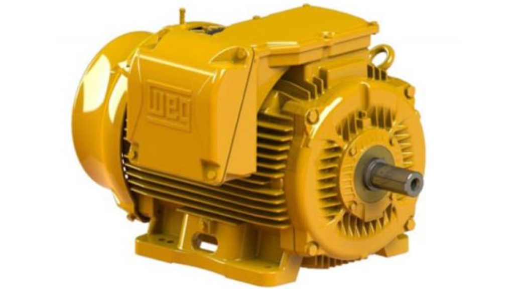
The insulation class of electric motors is critical for ensuring safe and efficient operation. It determines the maximum temperature a motor can withstand without compromising its lifespan, being directly influenced by the insulating materials used in the motor’s construction. In this article, we will explore the concept of insulation class, the importance of insulating materials, the most common insulation classes, and how to choose the most appropriate one for each application, based on standards such as IEC 60034-1 (International) and UL 1446 (USA).
The insulation class of an electric motor refers to the ability of the insulating materials used in its construction to withstand the temperatures generated during operation. These materials are essential to prevent the deterioration of the motor’s internal components, protecting them from excessive heat that could cause electrical failures.
The insulating materials used in electric motors are designed to withstand high temperatures and harsh operational environments. The choice of insulation material is based on the maximum temperature it can handle without losing its properties. Some of the most common insulating materials include:
Each of these materials is selected based on the temperature the motor will experience during operation. The correct material choice ensures that the motor operates efficiently and without failure, even under extreme temperature conditions.
Choosing the appropriate insulation class for an electric motor is essential to ensure it operates within safe thermal limits. Running a motor beyond its temperature limit can lead to the degradation of insulating materials, causing motor failures and necessitating repairs or replacement prematurely.
According to international standards like IEC 60034-1, insulation classes are categorized based on the maximum temperature the insulating materials can withstand. The most common classes are:
Each of these classes has been developed to withstand different temperature levels, ensuring the motor functions efficiently in various operational conditions.
Among the various classes available, Class B and Class F are the most commonly used in the market. Motors manufactured with these classes use insulating materials that can withstand temperatures up to 130°C (266°F) and 155°C (311°F), respectively. The choice between these classes depends on the motor’s operating conditions, such as ambient temperature, load, and duty cycle.
Choosing the correct insulation class should consider several factors, including:
For most industrial applications, Class B is sufficient. However, under more severe conditions or demanding duty cycles, Class F is recommended.
If you liked this article, consider sharing it on social media, this will help to spread knowledge, leave your comment below so we can know your opinion.
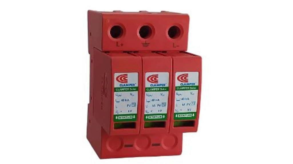

Surge protection in electrical installations is essential to ensure the safety and integrity of equipment and electrical systems. Surge Protection Devices (SPDs) play a crucial role in this process by diverting excessive energy caused by lightning strikes or other anomalies to the grounding system, thereby protecting the installation. This article provides a comprehensive guide to SPDs, covering their types, operation, relevant standards, and best installation practices.
What Are Surge Protection Devices (SPDs)?
SPDs are devices designed to protect electrical installations from voltage surges, which can be caused by phenomena such as lightning strikes or switching operations within the electrical network. These devices are connected between the phase and ground of the installation, diverting the surge to the grounding system and protecting the connected equipment.
Standards and Regulations
In the United States and the United Kingdom, the primary standard governing the installation and use of SPDs is the IEC 61643 series of international standards. These standards define guidelines for the protection of structures against lightning strikes and detail the requirements for SPD installation, including classification and positioning within the electrical system. For the UK, the BS EN 61643-11 is commonly referenced for low-voltage systems.
Classification of SPDs
SPDs are classified into different categories based on their capacity to withstand and dissipate surges:
How SPDs Work
SPDs act as a kind of relief valve for excessive energy. Under normal conditions, they have high resistance, isolating the live conductors from the ground. When a surge occurs, the resistance of the SPD drops significantly, allowing the surge current to be diverted to the ground, preventing damage to equipment.
There are two main types of SPDs based on their electrical action:
Types of SPDs by Technology
SPDs can be built using various technologies, each with specific characteristics:
Installation Topologies
The installation of SPDs must follow specific topologies, such as the TN-S and TN-C systems, to ensure the surge is effectively diverted to the ground. Additionally, it is common to use fuses in series with the SPD to add an extra layer of protection.
Lightning Protection Zones (LPZ)
Electrical installations are divided into Lightning Protection Zones (LPZ), which vary depending on the severity of the surges that may occur. SPDs are installed at the boundaries of these zones:
Best Practices for Installing SPDs
FAQ about Surge Protection in Electrical Installations
If you liked this article, consider sharing it on social media, this will help to spread knowledge, leave your comment below so we can know your opinion.